
Like any manufacturing process, injection molding has its advantages and disadvantages. Some parts are easier to mold than others, and things can quickly go wrong if you don’t know what you’re doing.
For novices experimenting with their first injection molded parts — or even for experienced engineers who usually go with other processes — it’s easy to fall into certain traps that lead to weak, unsightly, or deformed parts.
This article looks at five common mistakes made during injection molding, including advice on how to avoid them.
1. Variations in wall thickness
Unlike CNC machined or 3D printed parts, which can take many forms, injection molded parts often look similar: thin, shell-like objects without any deep sections of solid material.
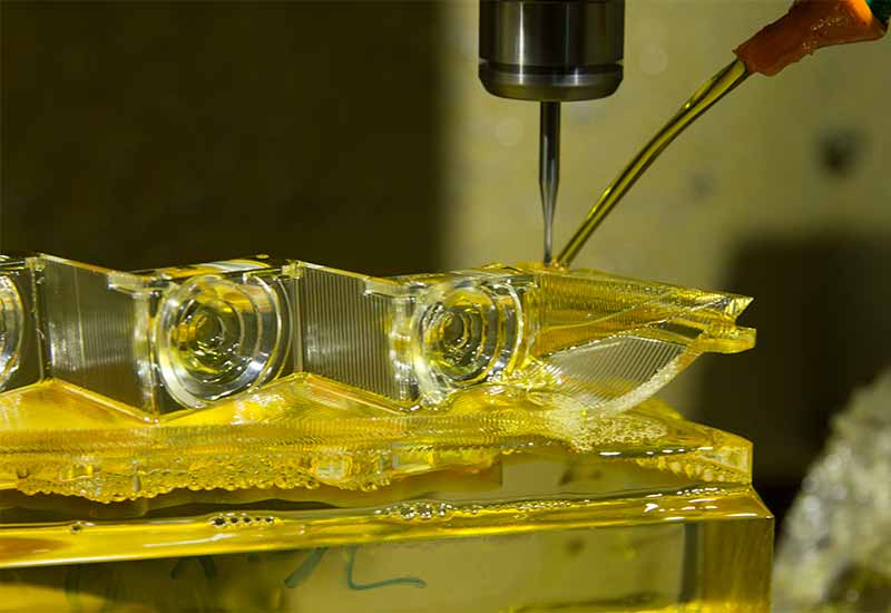
This is because of the way injection molding works. When a mold is filled with liquid material, that material must cool down to become solid; if some areas cool down faster than others, the cooler areas solidify and shrink before the others, causing stresses that result in the warping of the part.
A way to avoid this warping is to ensure that no areas are dramatically thinner than others, since thinner areas cool faster. An ideal situation is to have fully consistent wall thicknesses, but if that is not possible, the transition between thin and thick should be as gradual as possible.
Rules to follow:
- Thin walls should be no thinner than 40% the thickness of adjacent walls
- Materials like Polyurethane and Long-fiber reinforced plastics cannot accommodate thin walls
2. CAD files converted from other formats
When designing an injection molded part, you need to start from scratch, tailoring every step of the product lifecycle to the injection molding process.
This means you cannot just take, for example, a 3D printing file like an .STL and convert it into an injection molding format. Even if you turn the .STL into a .STEP file, the result will be a 3D object originally made up of triangles, whereas injection molding interprets shapes as a series of curves.
While reverse engineering software packages exist for turning .STL files (back) into a different format, they require as much expertise — or more — as designing a new part.
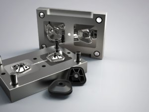
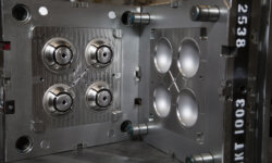
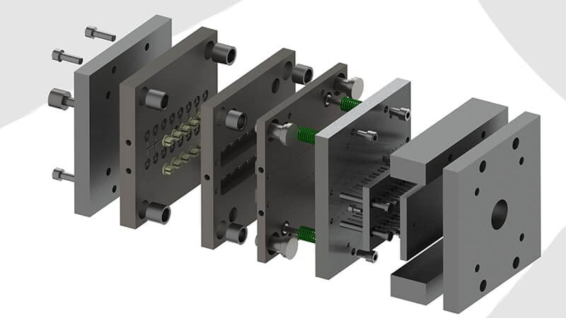
3. Parting lines in the wrong place
In the process of injection molding, the parting line is the dividing line between the core and cavity molds. Its placement can affect the success and cosmetic appearance of the molded part.
Improper parting line placement can cause issues such as:
- Flash, where material leaks out of the tiny gap between the mold core and cavity
- Need for additional ejection steps
Parting lines should ideally be placed along sharp edges. This both makes the line less visible and reduces the chances of flash and other undesirable effects.
Many CAD software packages include parting line analysis, helping you decide on the ideal placement. However, your software probably cannot comprehend the eventual real-world application of your part, which is also a big factor when determining line placement.
4. Using less than 1 degree of draft
During injection molding, draft or taper is an angle incorporated into a design to make it easier to eject the mold. Draft can also reduce warping or breakage of a part.
One of the most common errors in injection molding design is forgoing draft — or not incorporating it until late in the design process when doing so will affect the otherwise finished design in a negative way.
Rules to follow:
- Add 1 degree of the draft for each inch of cavity depth
- 0.5 degrees for vertical faces
- 3+ degrees for a shutoff
Also bear in mind that the draft relates to the parting line: the line must be located so it splits and therefore minimizes the draft.
5. Undercuts
Undercuts are protrusions, recessed areas, or other features that would prevent a part from being ejected from a simple two-part mold. Examples of undercuts include connecting clip tabs on plastic containers and threads on fasteners.
Injection-molded parts are much easier (and cheaper) to fabricate if the design is free of undercuts, so all efforts should be made to eliminate them from the design.
If the feature is essential to the part, there are some workarounds, including side-actions, bumpoffs, and telescoping shutoffs, but these will increase both cost and lead time. Altering the parting line may mitigate the problem of the undercut.
Undercuts also present a problem in CNC machining, when an end mill cannot reach a feature due to its placement. Some prototypes with difficult undercuts may be suitable for 3D printing with support structures.
3ERP is a rapid prototyping specialist with years of experience making injection molding parts. Contact us for a free quote on your next project.