
Milling is one of the most popular machining processes. Milling machines are present in almost every machining workshop. The benefits and capabilities of these machines are far-reaching.
People new to the industry often ask what is milling, its working process, and its various types. This article will have an in-depth discussion on the milling technology. It will provide a lot of beneficial information for beginners and professionals alike. Additionally, it contains many tips for improving the quality of milling operations.
What is Milling?
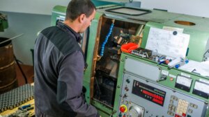
A modern milling machine is often paired with Computer Numerical Control (CNC) for automated control over the whole process.
History of Milling
Traditionally, the crafting of complex shapes was done with manual hand filing. Hand filing created the requirement for a highly skilled laborer.
In the early 19th century, milling machines began to replace these processes. A milling machine eliminated the manual filing skill requirement. Instead, operators could use these machines with little expertise. Only short training on the machine was needed.
Initial milling machines found application in making rifle parts for the army. The milling machines were manually operated until the middle of the 20th century.
With the rise of computing technology, milling machines integrated with CNC technology in the 1950s. This gave birth to the modern automated milling machines used industry-wide today.
Who invented Milling Machine?
Eli Whitney invented the first milling machine in 1818. The purpose of this milling machine was to manufacture rifles for the US government. The basic design and features of this machine were so perfect that the same carried on for over 150 years. Incidentally, Eli Whitney is also credited with inventing the first cotton gin.
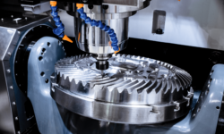
How Does Milling Work?
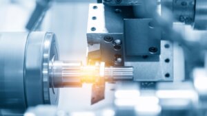
The main working part of a milling machine is the rotary cutting tool. This cutting tool is responsible for the material removal process. Milling machines can utilize both single-point and multi-point cutting tools.
The cutting tool in milling moves perpendicular to the rotational axis. For instance, if the cutting is rotating in the X-Y plane around the Z-axis, the movement of the cutter also occurs in the X-Y plane. The workpiece meets the cutter at the rotating tangent, resulting in the material removal process.
What are the Different Stages in the Milling Process?
Here is a step-by-step breakdown of the working process of milling machines:
- Workpiece Loading: The preliminary setup involves keeping the workpiece on the machine table feed and securing it. Wobbly fixtures will result in machining errors and poor precision.
- Tool Selection: Many different types of milling machine tools exist. Choose the right tool for the job, which depends on the workpiece materials and the required result.
- Machine Setup: Machine setup involves adjusting parameters like spindle speed, coolant flow, feed rate, cutting depth, etc.
- Milling Execution: The operator starts the actual milling operation once the setup is complete.
- Roughing: Roughing is the process of removing abundant material from the workpiece. This is done to get the workpiece into a vague resemblance of the required shape. This is done at a high cutting speed and feed rate.
- Semi-finishing: Once roughing completes, the speed of the milling machine is reduced. The workpiece is shaped identically to the final part.
- Finishing: Finishing occurs at a very slow feed rate and low depth of cut. The aim is to improve the dimensional accuracy of the part and make it as close as the machine possibly can.
- Unloading: The operator removes the finished part from the milling machine.
- Inspection and Quality Control: The final part is inspected to ensure there are no flaws. In case of any defects or further machining requirements, the operator loads the part on the machine and goes through a further finishing pass. This stage repeats until the part meets the required standards.
- Post-processing: The part can undergo any secondary machining requirements after milling. Common post-processing steps are deburring, cleaning, grinding, surface treatment, etc.
Types of Milling Operations
There are many different types of milling operations. Each of these types can create different components of shapes. These different types are:
- End Milling: An end mill is similar in shape to a drill bit. However, end mills are able to cut radially and axially. The drilling machine can only cut in the axial direction. A conventional milling machine can cut only in the radial direction.
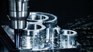
- Face Milling: A face mill is used when working on the surface finish of a workpiece. Face mills can turn an uneven surface into a flat surface. It can also create very smooth surface finishes. There are different automatic and manual milling options for face milling.
- Chamfer Milling: Chamfer milling machine is used to make chamfers and bevels. A chamfer mill is also known as a chamfer cutter. Chamfer mills also have other applications like deburring, countersinking, and spotting.
- Slot Milling: Slot milling uses a long rotary cutting tool to create grooves in a workpiece. It is also known as groove milling. The slots made by this machining process are deeper than what end mills can create. The grooves can be closed or open, with many options for shapes.
- Peripheral Milling: In peripheral milling, the cutting tool is placed parallel to the workpiece. Therefore, the sides of the cutting tool grind against the work surface instead of the tool tip. This is the opposite of the face-milling process. Peripheral milling is preferable when a large amount of material removal is required.
- Climb Milling: In climb milling, the cutting tool rotates in the feed direction. This is the opposite of conventional milling operations, where the cutting tool rotates opposite the feed direction. The cutting tool climbs over the workpiece resulting in an accumulation of chips behind it. This eliminates the problem of chips obstructing the cutting tool.
- Profile Milling: The profile milling process is used when machining vertical surfaces or vertically inclined surfaces. It can be used in the roughing as well as the finishing stage. Different types of cutting tools in profile milling are based on roughing or finishing operations.
- Helical Milling: Helical milling makes helical pathways, channels, and holes in a cylindrical workpiece. The workpiece is present on rotary tables. The rotating cutter moves along a helix angle along the workpiece. Helical milling is a common type of process for making lubrication holes and path on a workpiece.
- Plunge Milling: In plunge milling, the feed is in the same direction as the tool axis. This process is also known as z-axis milling. Plunge milling is commonly used in the roughing stage. The cutter plunges into the workpiece and carves out pockets in the material.
- Thread Milling: Thread milling is used to make threads inside a workpiece. Thread mills work on predrilled holes only. The thread mill rotates as well as revolves around the interior surface. Thread turning is more commonly used than thread mills.
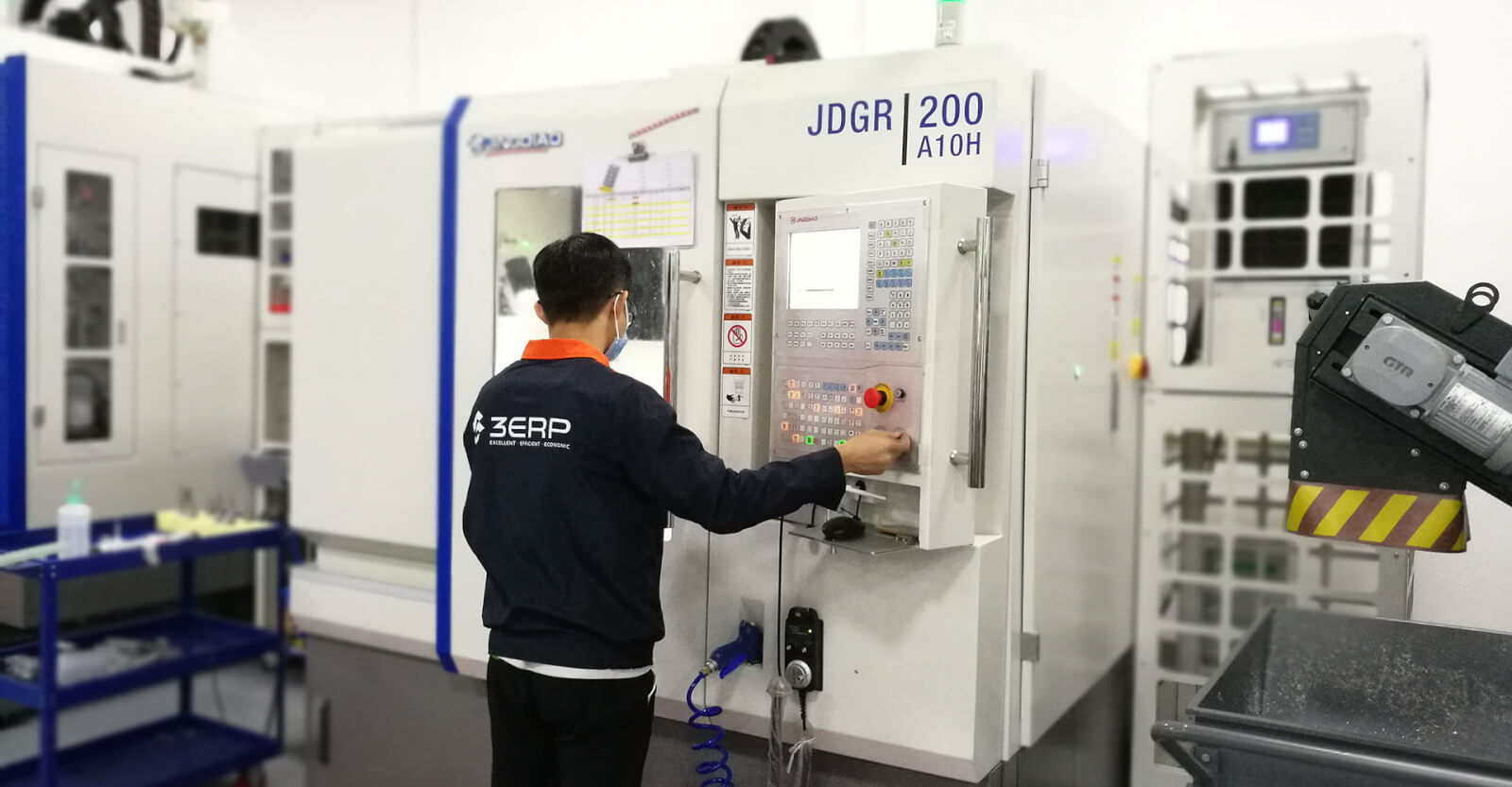
- CNC Milling: CNC stands for Computer Numerical Control (CNC). CNC milling utilizes computer programs to control the cutting tool’s motion. It can create parts of high complexity at fast speeds. Depending on the complex shapes required, there are multiple axes options for CNC milling machines.
What is the most common type of milling process?
End milling and face milling are the most common types of milling process. These are used in conjunction with most other machining processes. These milling processes can craft the surface and the interiors of the workpiece.
What is the Equipment Used in Milling?
Milling requires a dedicated set of equipment and an in-depth knowledge of how it works. Here are the different tools used in the milling process:
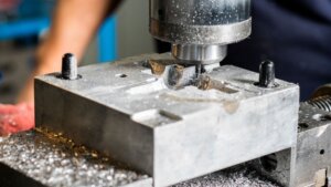
Milling Machine
The milling machine houses the movement mechanism for the tool and the workpiece. The size of the machine depends on the dimensions of the part that requires milling. A milling machine contains several components like the worktable, monitor, knee, column, base, saddle, quill, spindle, and more. The particular parts in a milling machine highly depend on the type of mill being used.
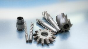
Milling Cutter
The milling cutter is the tool bit used in a milling machine to remove material from the workpiece. Milling cutters always have a rotational ability due to the nature of the milling operation. The particular design of the milling cutter is highly variable depending on the milling process. Some of the common types of milling cutters are:
Horizontal Milling Machine
- End Mill: The end mill is a long and narrow cutting tool with a sharp end. The cutting teeth are present on the side and the end. The bottom of the end mill can be flat, rounded, or radiused.
- Face Mill: Face mill has multiple cutting points on the side of the cutter. Therefore, face mills cut the workpiece horizontally. The cutting points are made with removable carbide inserts. The inserts can be attached by screwing on the face mill. This leads to a highly efficient mill operation.
- Slab Mill: Slab mill cutter is used for machining planes. It is also known as a plane mill. There are multiple cutting teeth present on the periphery of the cutter. The teeth may be straight or spiral.
- Shell Mill: Shell mill is a modified design of a face mill. It contains a bow that can host an arbor for mounting additional inserts. Sometimes, shell mill is used interchangeably with face mill.
- T-slot Cutter: A T-slot milling cutter is used to machine undercuts. It can widen the bottom part of an existing groove in a part. This results in a ‘T’ shaped groove. It is used for making machine tooling and keyways.
- Fly Cutter: A fly cutter is a single-point cutting tool. It is used for machining a flat surface on a large area. It is similar to lathe cutters. The cutting edge is generally a replaceable carbide insert.
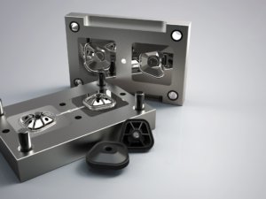
- Ball Nose Cutter: Ball nose cutter is common for machining dies and molds. It is similar to an end mill with a hemispherical rounded end. A ball nose cutter is also called a ball mill or full radius end mill.
- Double Angle Mill: Double angle mill is a highly versatile cutting tool. It can create threads, chamfers, back chamfers, countersinks, bevels, grooves, and slots in a workpiece. It can also help in machining surface finish processes such as deburring.
- Staggered Tooth Mill: Staggered tooth mill is used for making slots of high depth. The staggered tooth design aims to remove the chips from the work surface. This prevents the chips from interfering with the cutting tool operations. It results in a longer tool life and cleaner cutting operations.
- Form Mill: Form milling cutter creates contours on a work surface. The contours can have any shape, such as concave, convex, straight line, and irregular shapes. It can also create rounded corners.
- Slot Mill: A slot mill cutter is also known as a slot drill. It has a flat end and two flutes. The periphery of the flutes cuts slots on the workpiece. There are many different sizes and pitches of slot milling cutters available. The ideal size depends on the slot dimensions.
- Woodruff Mill: Woodruff mill makes keyways in horizontal milling machines. It has a flat end and multiple cutting teeth on the sides.
Vertical Milling Machine
- Flat-end Mill: Flat end mill is also called square end milling cutter. These cutters have multiple functions in vertical milling machines. Typical processes are plunging, face milling, side milling, grooving, and counter-boring.
- Ball-end Mill: Ball-end mills have a hemispherical bottom face. The purpose of ball-end mills in a vertical milling machine is to create rounded grooves. Grooves for metal bearings in machines are commonly made with a ball-end mill.
- Chamfer Mill: Chamfer milling cutter is used for the edge treatment of the workpiece. It creates rounded corners in chamfers and bevels.
- Twist Drill: Twist drill bits have multiple flutes converging at a single point. The number of flutes varies between two, three, or four. The purpose of a twist drill is to cut metals and wood.
- Reamer: Reamer is used for enlarging holes made previously with a boring or drilling machine. Precision reamer provides a small enlargement of all but a high degree of accuracy. Non-precision reamer can give a higher enlargement but with low accuracy. Reamer is also used for improving the surface finishes of a hole.
- Tapping Mill: A tapping mill or tap is used for making threads in a hole. Generally, tapping is preferable for holes that pass entirely through a workpiece. Tapping can provide a high-speed operation compared to thread milling process.
Prolonging Milling Tool Life
Tool life is a crucial parameter when it comes to milling cutters. Understanding tool life and how to prolong it can result in significant savings in milling costs and the generated waste.
What is Tool Life?
Tool life is the time period of useful operation of a cutting tool. It is the lifespan of a tool from its first use to the point it stops providing desirable results. An important thing to note is that tool life is not limited to tool breakage. A tool can be at the end of its life even if it has not broken but has stopped providing required milling results. At the end of tool life, you need to replace the tool.
Tool life is a major factor in the operational costs of a milling machine. Low tool life means a higher tool replacement. This can lead to a significant increase in the running costs of milling machine tools.
What is Tool Wear?
Tool wear is the degradation of the cutting tool due to operation. Tool wear occurs in all machining processes. The rate of wear can vary on the tool material, build quality, and how the operator uses the machine.
All tools come with an estimated tool life. However, the tool usage considerably varies between applications. Therefore, the exact tool wear and tool life cannot be determined beforehand. The operator needs to inspect the tool regularly to analyze wear. The operator can decide if more tool life remains based on examining the tool wear.
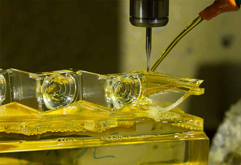
What is Cutting Fluid?
Cutting fluid is a type of compound that reduces tool wear and prolongs its life. It is common when milling metal materials. Cutting fluid is known by many other names, such as lubricant, coolant, cutting oil, or cutting compound. Cutting fluid provides multiple benefits:
- Heat Dissipation: Cutting metal with milling generates a lot of heat. This heat results in faster tool wear. The cutting fluid absorbs this heat and lowers the tool’s temperature, reducing tool degradation.
- Lower Friction: Cutting fluid lowers the friction coefficient between the metal and the cutting tool. This results in a faster cutting process and further reduces the tool wear.
- Chip Removal: Chips often stick to the cutting surface due to high heat. This obstructs the movement of the cutting tool and increases tool wear. Cutting fluid prevents chips from hindering the process and avoids welding of chips with the work surface.
Types of Cutting Fluids
There are many different types of cutting fluids for the milling process. These types are:
- Liquids: Liquids are the most common type of cutting fluids. There are three classes of liquid cutting fluids: mineral, semi-synthetic, and synthetic. Mineral oils are petroleum-based cutting fluids. Synthetic oils are water-based compounds.
- Paste: Liquid cutting fluid is not suitable for all applications. Therefore, cutting fluid is also available in paste and gel form.
- Aerosol: Aerosol cutting fluid is sprayed on the work surface. These are not highly preferred due to the dangers to workforce health.
- Air-based: Air-based cutting fluids use gases such as nitrogen. These are new and evolved types of cutting fluids. Generally, these are used when milling tough materials like titanium and Inconel. It can lead to a ten times longer tool life.
What are the Key Parameters in Milling?
The important parameters for milling machining process are:
- Feed Rate: Feed rate is the relative speed of movement between the cutting tool and the workpiece during the CNC milling process. This value is measured in millimeter per minute (mm/min) or inches per minute (IPS or in/min).
- Depth of Cut: Depth of cut is the vertical thickness of material removal in a single pass. It can be measured in inches or milimetres. A higher depth of cut leads to a slower cut and a higher tool wear.
- Spindle Speed: Spindle speed is the speed at which the tool (or spindle) rotates. It is measured in revolutions per minute (RPM). A higher spindle speed leads to a faster cutting and a higher rate of material removal process.
- Axial Depth of Cut: Axial depth of cut is the length of cut measured axially in the direction of the cutting tool. This value is also the width of the cut in a single pass. The axial depth of cut determines the chip thickness.
- Radial Depth of Cut: Radial depth of cut is measured along the radius of the cutting tool. This value is also the diameter of the cut on the workpiece. It determines the deflection of the milling machine tool.
- Tool Diameter: Tool diameter is the diameter of the particular milling cutter. It can be measured in inches or mm. Tool diameter determines the dimensions of the cut, the cutting forces, and chip evacuation.
- Cutting Speed: Cutting speed denotes the rate at which the tool moves along the workpiece. This value is obtained by multiplying the circumference of the tool with the spindle speed. This value is measured in surface feet per minute (SFM) or metres per minute (m/min).
- Tool Overhang: Tool overhang is the distance between the tool holder and the tool edge. This distance can be seen as the functional length of the tool. A larger tool overhang increases the vibrations, reduces stability, and increases the tool wear.
- Coolant Flow Rate: Coolant flow rate is the rate at which cutting fluid flows to the work surface. The coolant flow rate is adjusted according to the cutting speed and the feed rate.
- Tool Coating: Special coatings are applied on milling tools to increase cutting quality and reduce tool wear. Common tool coatings are Diamond Like Carbon (DLC), Titanium Nitride (TiN), and Titanium Aluminum Nitride (TiAlN).
- Stepover: Stepover is the distance between two back to back passes during milling. Too low stepover can result in interfering cuts leading to poor precision and errors.
- Ramp Angle: Ramp angle is the angle of contact between the milling tool and the workpiece during entering. This angle is used during ramping operations.
Acceptable Standards for Milling
Learning about the milling standards can help know what to expect from the milling operation.
Tolerance
Machining tolerance is the deviation of the milled cuts from the intended cuts in the blueprint. A lower tolerance means a higher accuracy of operation. CNC milling machine tools can create parts with tolerance as low as ± 0.005″ (approx. 0.13 mm). This is a very low value which gives high-precision features to the milling process.
For plastics, the tolerance is higher at around ± 0.010″. This is due to the effect of plastic deformation and heat.
Minimum Wall Thickness
Parts made with milling require a minimum wall thickness. Walls thinner than this value can often collapse during milling or later operation. The minimum wall thickness value is 0.5 mm for metals and 1.0 mm for plastics.
However, it is recommended to go over this value to keep some margin of error. The recommended values are 0.8 mm for metals and 1.5 mm for plastics.
What are the Advantages of Milling?

There are many benefits that milling has to offer over alternative manufacturing processes. These benefits are:
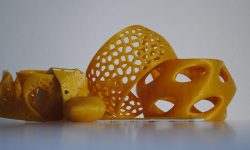
- Versatile: Milling is a very versatile process. It can create a wide range of shapes on many different types of materials. Alternative manufacturing processes like 3D printing are limited in terms of materials.
- Precision: CNC milling is one of the most precise manufacturing technology. It is the go-to process in fields such as aerospace, where precision is paramount.
- Efficient: Milling has a very high efficiency. CNC milling can create parts at a rapid pace that is suitable for mass production.
- Quality: Milling is a high-quality process. The parts created by milling usually do not require secondary surface finishes.
- Automation: Milling is often integrated with CNC machine tools. This makes the whole process automated, reducing the labor requirement and increasing the production rate.
- Cost-effective: The high production rate and low labor costs lead to a very cost-effective operation.
- Consistent: The high precision of milling makes very consistent parts. This is important for making commercial parts where repeatability is the key.
- Machining Hard Material: Milling can easily machine hard materials like titanium and Inconel. These materials are tough to machine with alternative technologies.
Common Milling Materials
Milling can work on a wide range of workpiece materials. Some common materials that undergo milling are:
Metals
Metals are the most common class of materials that undergo milling. Milling can create parts from any type of metal. This includes hard metals like titanium and soft metals like copper. Some of the metals and alloys best suited for milling operations are:
- Aluminum
- Stainless Steel (all grades)
- Carbon Steel
- Copper
- Nickel
- Chrome
- Bronze
Plastics
Milling of plastic parts is common for high precision parts or to produce parts at a large scale. When milling plastics, monitoring temperature is important. This is because plastics can undergo deformation in the presence of heat. Common types of milled plastics are:
- ABS
- Nylon
- Peek
- POM
- Polycarbonate
Composites
Composite materials are common in sectors like aerospace due to extreme physical characteristics. These physical characteristics also lead to poor machining by conventional processes. However, milling can work on these materials with ease. Commonly milled composites are:
- FRP
- Carbon
- Metal Matrix Composites
- Polymer Matrix Composites
- Ceramic Matrix Composites
Woods
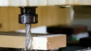
Milling can work on a wide variety of woods without causing any adverse effects. Milling of wood is a common process in the furniture industry. These woods include:
- Hardwood
- Softwood
- Plywood
Ceramics
Ceramics can be hard to machine due to excessive chipping and brittle nature. To solve this, ceramics are milled before their final sintering. Commonly milled ceramics are:
- Alumina
- Macor
- Aluminum Nitride
- Boron Nitride
- Alumina Silicate
- Glass
- Graphite
- Quartz
Others
Besides the above materials, milling process is also common for materials like:
- Rubber
- Foam
- Stones like marble and graphite
Which Materials are Unsuitable for Milling?
Milling can work on most of the materials. However, certain materials can pose additional challenges during milling. Here are some of these challenging materials:
- Brittle Materials: Brittle materials have the problem of excessive chipping. These chipping often fly around in the workplace causing hazards. Additionally, there is also the risk of material cracking.
- High Hardness Materials: Materials with high hardness have poor machinability. Milling these materials causes tool wear at a rapid pace. This results in frequent tool replacements and a high milling cost.
- Reactive Materials: Milling can increase the temperature of the work surface significantly. Therefore, cutting materials with a reactive nature becomes very challenging.
Is Milling Expensive?

Yes, CNC milling can be expensive due to the high equipment cost. Good quality CNC mills can start at around $50,000 and go astronomically high. The operating expenses of milling are not high. It can start at around $40 per hour.
Therefore, the most cost-effective method to mill parts is to outsource the milling process. Most manufacturers choose 3ERP to handle all the machining operations. The parts can be created on the exact blueprint that you supply. This results in a very affordable operation without investing in the equipment itself.
Is Milling Process Safe?
Milling machines are capable of cutting the toughest materials in existence. These cutters can easily pierce through human body parts, making it very unsafe. Therefore, a milling machine should be operated only with a trained operator. Additionally, it is essential to use safety equipment and machine with all the safeguards.
What are the Hazards in the Milling Process?
Common milling hazards include:
- Sharp Cutter: The milling cutters are very sharp and rotate at extreme speeds. The cutter or any other rotating machine part should never have human contact during operation.
- Chips: Milling removes unwanted material in the form of chips. These chips fly at a high speed and can puncture the skin or sensitive organs like the eyes.
- Noise: Milling, like other industrial equipment, creates high noise levels. It requires proper noise-canceling ear protection.
- Heat: The process generates high temperatures that should not come in human contact. The parts can retain the high temperature for some time after the operation has stopped. Therefore, handling with gloves is essential.
- Electrical Hazard: The machines use extremely high voltage. It is important to cover all electrical parts with guards and label them as electrical hazards.
What is the Duration of the Milling Process?
The milling process lasts for a few seconds to a few minutes. The cutter movement is extremely fast. The main time taken is during the loading and unloading of the part.
Common Problems in Milling
There are certain problems that can be commonly encountered during milling operation. These are:
- Chatter: Chatter is a common issue when the tool is not mounted correctly. Chatter is also typical during the milling of corners. Chatter causes high vibrations, breaking the tool and creating defects in the parts.
- Tool Wear: Certain level of tool wear is unavoidable when it comes to milling. However, not optimizing the milling process can accelerate the wear and require frequent tool changes.
- Workpiece Deformation: The high heat and large cutting force can sometimes cause workpiece deformation.
- Chip Evacuation: Milling requires a proper chip evacuation strategy. Otherwise, the chips keep on re-cutting with the tool.
- Tool Collision: Tool collision occurs when the dimensions are not accurately accounted for.
Conclusion
Milling has been the most common industrial process since its inception over 200 years ago. The wide variety of milling operations can result in parts of any required shape. This makes milling the preferred operation, especially crucial in metalworking. Get in touch with 3ERP to receive an exact quote on how much milling will cost you for your next project.
Frequently Asked Questions (FAQs)
Here are the answers to some common questions regarding milling:
1. What is the golden rule in milling?
The golden rule in milling is- thick in, thin out. The operator should aim for thick chips when the tool enters the workpiece. The operator should aim for thinner chips during the later operation and tool exit from the workpiece. This results in a stable milling operation.
2. How accurate is the milling process?
Milling is one of the most accurate manufacturing processes. It can provide tolerance as low as ± 0.005″.
3. What is the difference between milling and turning?
There is a vast difference between milling and turning. Milling uses a rotary cutting edge against a stationary surface. On the other hand, turning uses a stationary cutting tool against a rotating surface.
4. What is the difference between milling and 3D printing?
There are a lot of differences between milling and 3D printing. Milling is a subtractive manufacturing technique. On the other hand, 3D printing is an additive manufacturing technique. Milling works on all materials, but 3D printing works only on certain plastics.