
Standard machining tolerances are an important parameter to consider regardless of the product you are manufacturing. In this day and age, most consumer goods demand consistency on a micro-scale.
Therefore, manufacturers often go through the various types of manufacturing processes and compare them while keeping the machining tolerances as a major factor. To understand the machining tolerances of different processes, it is vital to know the concept of machining tolerances, how to measure them, and the different types of tolerances that exist.
This article will go through all this information and more. In the end, there will be tips with which you can improve the machining tolerances for your own industry.
What are Machining Tolerances?

For higher accuracy and high precision, the value of machining tolerances should be the minimum. In simple terms, the machining tolerances are inversely proportional to the accuracy of a process.
Since there is no such thing as a perfect process, the value of machining tolerances can never be zero in practice. However, modern manufacturing techniques such as CNC machining have brought this value quite down and to the minimum.
Generally, tolerances in CNC machining are measured in the format ±0.x”.
Calculation and Expression of Machining Tolerances
Before knowing how to calculate machining tolerances, understanding the various terms associated with this subject is important. Here are some of the terminology that you should be familiar with:
Basic Size
The basic size of a workpiece is the size mentioned in the blueprints. Manufacturers and designers know that the manufacturing processes will have a certain level of tolerances. Therefore, designers choose the basic size keeping in mind the deviation that will occur during the manufacturing process.
Actual Size
The actual size is the dimensions of the final product after the machining process is finished. While the basic sizes are theoretical values, the actual size is the practical realization of the finished part. While it is almost impossible to make the actual size exactly the same as the basic size, manufacturers aim to bring these two values as close as possible.
Limits
Limits are the maximum and minimum allowed dimensions of the part. The maximum allowed dimension is called the upper limit and the minimum allowed dimension is called the lower limit. If the actual size of the part falls outside of these two limits, the part is considered unusable and rejected.
Deviation
Deviations are the variances of the maximum allowed size from the basic size. Since there are two types of maximum allowed size- upper and lower limits, there are two types of resultant deviations: upper deviation and lower deviation. Calculation of these deviations is easy:
- Upper Deviation= Upper limit – Basic Size
- Lower Deviation= Lower Limit – Basic Size
Datum
In physics, a datum is an imaginary line or plane chosen arbitrarily as a reference point for measurement tools. The concept of Datum is also used in many types of geometric dimensioning and tolerancing areas, which will be discussed in the sections to come.
Maximum Material and Least Material Requirements

Maximum Material Condition (MMC) occurs when a feature or segment of the workpiece contains the maximum amount of material in all places. Examples of MMC can be the smallest size hole or the largest pin in a workpiece. The occurrence of MMC provides bonus tolerances to work with.
Similarly, the Least Material Condition (LMC) occurs when a feature or segment of the workpiece contains the least amount of material in all places. Examples of NMC can be the largest size hole or the smallest pin in a workpiece.
The use of MMC and NMC dictates the clearance fit for an assembly. MMC is the worst condition scenario in which the part would still fit. Any increase in size beyond the MMC would not allow the assembly of the product.
The shift from MMC to LMC allows for a greater allowed tolerance in the workpiece area, which is called the bonus tolerance. The calculation of bonus tolerance depends on how much lower material the actual part has compared to the maximum material. Therefore,
- Bonus tolerance = MMC – Actual Size
Since the lowest the actual size can be is the LMC limit, the maximum bonus tolerance will be:
- Bonus Tolerance (max) = MMC – LMC
Decimal Places
In high-precision processes such as CNC machining, tolerances occur in very small amounts. The actual value of tolerances in CNC machining is so low that it requires decimal places to measure it. A higher number of decimal places correlate to tighter tolerances and higher accuracy.
For better understanding, let us take a manufacturing process A with a tolerance of ±0.2″, B with a tolerance of ±0.1″, C with a tolerance of ±0.01″, and D with a tolerance of ±0.001″. In terms of accuracy, process D would be the most accurate followed by C, B, and A.
Calculating Tolerance

- Upper limit: 12 mm
- Lower limit: 8 mm
The tolerance of the machining process would be:
- tolerance (t) = upper limit – lower limit
- t = 12-8 = 4 mm.
Sometimes, instead of mentioning upper and lower limits, the limits are described in the form of variation, such as 10 ± 0.2 mm. In this case, the upper and lower limits can be calculated by adding and subtracting the variation respectively.
Different Types of Machining Tolerances

Unilateral Tolerance
Unilateral tolerances in CNC machining hint that the allowable variance can only occur in one direction. The basic size of the component is the same as the upper limit or the lower limit, and the tolerance can only be either positive or negative but not both.
For instance, if a pipe has a diameter of 10 mm with a unilateral tolerance of +1 mm, both the basic size and lower limits of the process would be 10 mm. The upper limit in this case would be 11 mm. All the acceptable parts should fall within this range, and any part smaller than the basic value of 10 mm will be rejected.
Similarly, if a pipe has a diameter of 10 mm with a unilateral tolerance of -1 mm, both the basic size and upper limit for the process would be 10 mm. The lower limit in this case would be 9 mm. The manufactured parts should fall between this range and all the parts even slightly larger than the basic value of 10 mm will be rejected.
Bilateral Tolerance
Contrary to unilateral tolerance, bilateral tolerances allow variation in both directions. The basic size of the component lies between upper and lower limits and the value of tolerance can be both positive and negative.
If there is an equal variation in both directions, the bilateral tolerances are mentioned as ±0.x mm. In case there is unequal variation, the bilateral tolerances can be written as +0.x mm and – 0.y mm.
To take an example, if there is a pipe with a diameter of 10 mm and a bilateral tolerance of ±1 mm, the basic size will be 10 mm, the upper limit will be 11 mm, and the lower limit will be 9 mm. All parts between 9 mm and 11 mm will be acceptable. Therefore, the actual part can be smaller or bigger than the basic intended part.
Limit Tolerances
Limit tolerances are another common expression of tolerances in CNC machining and other manufacturing methods. Limit tolerances do not use any ‘+’, ‘-‘, or ‘±’ symbolic language. Instead, the upper and lower limits of the part are mentioned. Instead of using the basic size and making the actual size fit within the permitted variance of the basic size, the only requirement is to make the part within the limits provided.
Limit tolerances are easy to use and eliminate the need for any calculations. If limit tolerance is depicted in a graph, the upper limit is stated over the particular dimension and the lower limit is stated under the upper limit and over the particular dimension.
An example of using limit tolerances is to machine a pipe with a diameter between 9 mm and 11 mm, instead of requiring a pipe between 10 ± 1 mm.
A major thing to remember is that while limit tolerances use different expressions than bilateral tolerances, the part outcome is going to be the same. The difference only comes in the ease with which the blueprint reader comprehends the design criteria.
Profile Tolerances
Profile tolerance is very different from the other types of tolerances mentioned above. While the other tolerances so far were variations in dimensional accuracy, profile tolerances relate to the curvature of the cross-section of the part. Its symbol is a semi-circle lying on its cross-section diameter.
For understanding the concept of profile tolerances in cnc machining, it is important to know what is profile line. Profile line is the line running along the cross-sectional area of a workpiece. Profile tolerance range implies that the curve of this line should be within the acceptable variance. This value is measured in dimensional units (mm or inches).
Orientation Tolerance
Orientation tolerance is the variation of a form of the workpiece in relation to a reference form. The reference form or plane used to check the relative variances is called the datum. Measuring orientation tolerance is done with regards to the perpendicularity of the workpiece or its angularity. Even when measuring a shift in angularity, orientation tolerance is also measured in mm or inches, instead of degrees.
Location Tolerance
The location tolerance range is similar to orientation tolerance. Location tolerance in CNC machining refers to the shift in the location of particular features of the workpiece. For measurement of the shift, a reference line called the datum is used. The intended position of the feature is called its true position.
Form Tolerances
Form tolerances pertain to the physical features of a workpiece, such as its flatness, roundness, or straightness. These tolerances are also measured in mm or inches, with measurement tools such as height gauges, calipers, micrometers, etc.
Runout Tolerance
Runout tolerance refers to the fluctuation of a particular feature of the workpiece with reference to a datum when the part is rotated 360 degrees around a central axis. Runout tolerance can be important and measurable for any or all features of the workpiece. The symbol for this tolerance is a square box containing an arrow pointing to the top right corner.
Unequally Disposed Tolerances
The unequally disposed tolerance band is also sometimes called the U modifier, due to its symbol being the letter ‘U’ in a circle. These tolerances are used when an unequal unilateral tolerance is required on a particular profile of the workpiece.
Geometric Dimensioning and Tolerancing (GD&T)
Geometric Dimensioning and Tolerancing is a system to detail and communicate the standard machining tolerances. Since there are many types of tolerances in many different types and shapes of parts, a standardized system helps various parties involved in manufacturing to communicate with each other. GD&T is the most widely adopted system of standard tolerances used across the globe.
GD&T assigns symbols for different types of tolerances along with a detailed set of rules on how to measure the particular tolerance band.
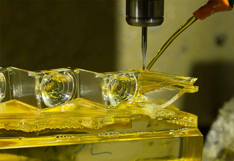
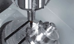
Common CNC Machining Tolerances
CNC machining is a wide field with many different processes under its umbrella. The CNC machining tolerances for each of these processes are different due to variations in the types of cutting tools used. Here are the standard CNC machining tolerances for common processes:
- Router: ± 0.005″ or 0.13 mm
- Lathe: ± 0.005″ or 0.13 mm
- Router (Gasket Cutting Tools): ± 0.030″ or 0.762 mm
- Milling (3-axis): ± 0.005″ or 0.13 mm
- Milling (5-axis): ± 0.005″ or 0.13 mm
- Engraving: ± 0.005″ or 0.13 mm
- Rail Cutting Tolerances: ± 0.030″ or 0.762 mm
- Screw Machining: 0.005″ or 0.13 mm
- Steel Rule Die Cutting: ± 0.015″ or 0.381 mm
- Surface Finish: 125RA
If you compare these values with alternative remanufacturing technologies, you will find that the CNC machining processes involve tighter tolerances.
Important Things to Remember When Dealing With Tolerances

Do you need tight tolerances?
Since tolerance directly reflects the accuracy of a part, the first look can make it appear that it is always better to have tight tolerances. However, for CNC machined parts, tight tolerances can increase the cost of production and lead to a time-consuming process. Therefore, use of tight tolerances should be incorporated when it is required.
Tight tolerances are generally needed in cases when a part is going to be used in secondary assembly processes. Loose tolerances in these cases can lead to a failure in acceptable assembly. Therefore, there is a high focus on the tolerance band.
Another use case of tight tolerance machining is when designing prototypes of innovative parts. Designers expect the prototype to function exactly like the finished product. Therefore, they use as tight requirements as possible.
Costs
For better optimization of resources, manufacturers do not aim for the absolute least tolerances. Instead, they use the least tolerances that will fit into their budget. A good way to incorporate the budget factor is by plotting the increase in cost with the reduction in the tolerance band, and finding out the acceptable range where these two values meet for the particular project.
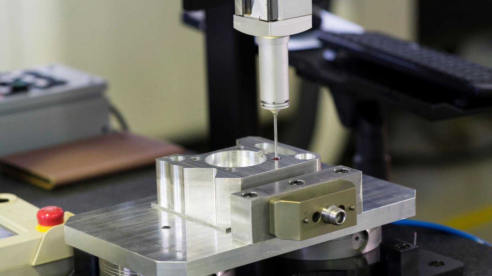
Inspection
Most projects made with CNC machines or any other manufacturing process have a quality control phase to check out if the final product is in the acceptable range. In case it fails to meet the acceptable range, the product is rejected.If using very tight tolerances, the time in the inspection stage is considerably increased. Additionally, complex equipment can be needed to measure the tighter tolerance level.
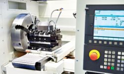
Machining Methods
CNC machines in general are appreciated due to their high precision and low specified tolerances. However, even within CNC machines, the type of machine used can significantly affect the part tolerances. Therefore, if you have CNC machines in-house, check the tolerance level of the machines beforehand and then design the project accordingly.
Surface Roughness
Every surface has rough aberrations on it regardless of how smooth it looks. For some surfaces, like polished natural stone, these aberrations are considerably smaller leading to lesser surface roughness. For others, like wood, the surface roughness is considerably higher. Therefore, when choosing tight tolerances for CNC machining, keep in the mind the already present surface roughness. Rough surfaces will bring difficulty when the goal is to achieve tight tolerances.
How to Find the Right Tolerance?

Using a Reputable CNC Machining Company
Outsourcing the project to a good CNC machining company can take out the headache of dealing with the technicalities of tolerances and many other things. 3ERP is one of the leading CNC service providers in this regard.
3ERP CNC machining services are provided by a team of skilled experts and the most advanced machines and equipment available in the market. This means that you not only have professionals suggesting the best tolerances to use, but you also have the best equipment that can achieve those tolerances in real life.
Self Calculation of Tolerances
To calculate the tolerance of the part yourself, you first need to envision the use of the part. The functionality of the part will dictate how much focus you need to pay to tolerances for the part. After that, you can use the general rules for determining tolerances.
Are There Any International Standards For Machining Tolerances?
Yes, there are many international standards for machining tolerances. The Geometric Dimensioning and Tolerancing (GD&T) itself contains seven different standards for measuring standard machining tolerances. Then there is also the ISO 2768 standards.
What is ISO 2768?
ISO 2768 is an international standard that specifies the general tolerances when making parts certified with international standards. It contains different classes in itself, such as:
- Linear dimensions
- External radii and chamfer heights
- Angular dimensions
- General tolerances for straightness and flatness
- General tolerances for perpendicularity
- General tolerances for symmetry
- General tolerances for circular runouts
Tips for Tighter CNC Machining Tolerances
Following the below tips can be helpful to get tight machining tolerances and higher quality parts:
- Remember that tolerances are not a one-size fits all designation. Calculate separate tolerances for different materials and for different applications. For metal parts, the standard tolerances are +/- 0.005″ and for plastic parts, the value is +/- 0.01″. These values can be more or less in practical realization due to varying geometric dimensioning.
- Choose a manufacturing process that can achieve the tolerances you require. While processes with tighter tolerances can be expensive, they can be overall cost-effective due to better optimization.
- Never underestimate the importance of parallelism and perpendicularity tolerances. These tolerances should be prioritized since any shift in these values can affect every other value, and even change the visual appearance of the part itself.
- The expectation of tolerance should be in line with the material’s machinability. Getting tighter tolerances requires more work on the material. This extra work can be very difficult for materials that are already hard to machine.
- If the project does not call for it, avoid using tight tolerances altogether. This can save up significant costs in the project.
- Place emphasis on tolerance for the important features of the part, such as features that aid in assembly or features that bear the stress. At the same time, tolerances can be ignored in some features, such as those there for aesthetic purposes.
What is considered a tight tolerance in machining?
While there is no exact range of tight tolerances, anything around ±0.005″ is considered a tight tolerance for CNC machining. Tight limit tolerance can go down to ± 0.001″, below which machining becomes highly challenging.
Importance of Machining Tolerances
The tolerance and dimensional accuracy of parts are much greater than what meets the eye at first. Every manufacturing process, whether manual or CNC, has a certain error to it, some more than others. The machining tolerances denote the extent of this error that can be allowed.
Keeping tolerances in mind allows for the production of high-quality parts. At the same time, ignoring tolerances can lead to serious manufacturing mistakes, causing the rejection of a large number of products or even entire batches.
Conclusion
Machining tolerances are an indispensable factor in manufacturing processes. While the degree of these tolerances can vary based on the projects, there are hardly any use cases in which these values can be completely ignored.
Therefore, placing due importance to the information mentioned above can be cost-saving to your project and lead to a better quality outcome. In case you feel the concept of tolerance is too technical, difficult, or hard to calculate for your particular project, 3ERP is always there to help.
Frequently Asked Questions (FAQs)
Here are the answers to some common questions regarding standard tolerances:
1. Which tolerance is the most difficult to machine?
Any tolerances below ±0.001″ are very difficult to machine. Keep in mind that this value is 25 micrometers, and one micrometer is a millionth of a meter. Therefore, such extremely low value is rarely encountered in real-life applications.
2. What are the most common machining tolerances?
The most common machining tolerances are standard tolerances falling between ± 0.005″ and ± 030″. These tolerances are applied when the clients do not have or do not mention their tolerance requirements.