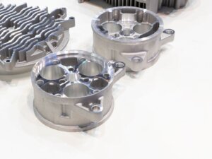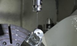

Computer Numerical Control (CNC) machining stands as a cornerstone in modern manufacturing, a process where pre-programmed software dictates the movements of factory tools and machinery.
The precision and efficiency of CNC machining and modern CNC milling tools have revolutionized production, yet the intricate nature of these operations brings inherent challenges, notably in the form of machining defects.
Understanding these defects and implementing solutions is crucial for maintaining the high precision component manufactured, ensuring quality, and minimizing costly downtimes.
What is CNC Machining?
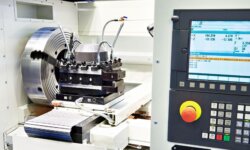
At its core, CNC machining is the automated control of machining tools and systems, including milling machines, CNC lathes, and grinders, by means of a computer. This manufacturing process transforms a digital model into a final part through successive material removal techniques.
The significance of CNC machines lies in their ability to produce complex parts with high precision and repeatability, pivotal in industries ranging from aerospace to automotive.
What are Common CNC Machining Defects and How to Fix Them?
CNC machining, despite its advanced nature, is not immune to defects. These defects can range from surface irregularities to tool breakage, each affecting the final quality of the machined part. Addressing these defects is not just about rectifying errors; it involves a comprehensive understanding of the machining process, tool material, and workpiece material.
Surface Finish Irregularities
Surface finish irregularities in CNC machining operations manifest as deviations from the expected quality of the machined part’s surface. They can appear as rough textures, lines, or unevenness, directly affecting the part’s functionality and aesthetics.
Cause:
- Chatter and Vibration: Excessive vibration in the CNC machine tools or cuttes can lead to uneven surfaces. This is often caused by blunt tools, incorrect CNC milling strategies like mixing climb and conventional milling, or inadequate cooling.
- Inappropriate Cutting Parameters: Wrong settings, such as too fast feed rates, can cause the tool to vibrate and leave uneven marks.
Solution:
- Regular Maintenance and Correct Strategy: Ensuring the cutting tools are sharp and using the correct milling strategy are crucial. Consistent maintenance can prevent tools from becoming blunt and causing chatter.
- Optimizing Cutting Parameters: Adjusting the feed rate and spindle speed appropriately can help in achieving a better surface finish. The use of full climb milling for precision side surface machining can also be effective.
Burn Marks
Burn marks on the surface of the workpiece indicate overheating during the process, usually evidenced by discolored patches on the machined part.
Cause:
- Incorrect Cutting Parameters: A poorly chosen combination of feed and speed can result in significant damage due to overheating.
- Insufficient Cooling: Lack of adequate cooling can lead to overheating, especially in materials like titanium that have poor thermal conductivity.
Solution:
- Adjusting Speed and Feed Ratio: Reducing the cutting speed relative to the feed rate can lower the machining temperature. Improving the cooling rate of the process is also critical.
- Enhanced Cooling Strategies: In cases of materials with poor heat conduction, both lowering speed and enhancing cooling may be necessary.
Dimensional Inaccuracies
Dimensional inaccuracies in CNC machining occur when the machined parts do not adhere to the specified dimensions, leading to issues in fit, function, or both.
Cause:
- Machine Calibration Errors: Inaccuracies often stem from calibration issues with the CNC machine itself.
- Material Inconsistencies: Variations in the material being machined can also lead to dimensional inaccuracies.
- Environmental Factors: Factors such as temperature and humidity can affect both the machine and the material, leading to size variations.
Solution:
- Regular Calibration: Routine calibration of the CNC machine ensures greater accuracy.
- Material Quality Control: Using stable and consistent materials can reduce variances.
- Environmental Control: Managing the machining environment helps mitigate external influences on the machining process.
Chatter Marks
Chatter marks in CNC machining are characterized by a series of regular, wavy lines on the machined surface, indicating vibrations during the cutting process.
Cause:
- Unwanted Vibrations: These marks are primarily due to vibrations between the cutting tool and the workpiece.
- Machine Tool and Workpiece Interaction: Issues with tool stability like unstable machine foundation, workpiece rigidity, or cutting conditions can exacerbate these vibrations.
Solution:
- Optimize Cutting Conditions: Adjusting the cutting conditions, such as speed and feed rate, can reduce vibrations.
- Improve Workpiece Rigidity: Ensuring the workpiece is securely fixed and supported can mitigate this issue.
- Vibration-Damping Tools: Using tools designed to dampen vibrations can provide a smoother finish
Burrs
Burr formation in CNC machining is a frequent issue where small protrusions or raised edges occur on the machined part, especially at edges or corners. These defects can affect both the part’s aesthetic and functional aspects.
Cause:
- Excessive Material Deformation: This occurs during cutting, particularly with softer materials or blunt tools.
- Improper Tool Path Settings: Incorrect settings can lead to burr formation.
- Chipping of Material: Often occurs in small chips or fragments on the cutting tool’s edge.
Solution:
- Deburring Processes: Manual removal using tools like files or sandpapers, and advanced deburring techniques like thermal and vibratory deburring.
- Tool Optimization: Using appropriate cutting tools and ensuring sharpness.
- Process Adjustment: Altering the machining process, like modifying tool paths and using suitable chip breakers or chip deflectors, can be effective.
Tool Marks
Tool marks in CNC machining refer to visible lines or ridges left on a machined surface, typically due to the interaction of the cutting tool with the workpiece.
Cause:
- Incorrect Tool Selection: Aggressive cutting parameters, improper machining tool selection, and machining material issues.
- Machine Vibration: Machine conditions and setup can cause these marks.
- Tool Entry and Exit Strategy: The way a tool enters and exits a workpiece can leave different marks.
Solution:
- Optimize Cutting Parameters: Adjusting the pressure applied by the tool.
- Tool Selection: Using tools with different geometries or coatings.
- Finishing Operations: Utilizing grinding or polishing to remove any remaining marks.
Deformation
Deformation in CNC machining occurs when the machined part undergoes bending, twisting, or changes in shape that were not intended in the design.
Cause:
- Internal Stress Release: Often associated with the release of internal stresses within the material.
- Insufficient Support: Lack of adequate support during machining.
Solution:
- Appropriate Machining Methods: Selecting suitable methods and using fixtures and supports can prevent deformation.
- Post-Machining Stress Relief: Techniques like thermal treatment can be used to relieve internal stresses and reduce deformation
Built-up Edge (BUE)
Built-up Edge (BUE) is a phenomenon in CNC machining where chips adhere to the tip of the cutting tool due to high cutting pressure and frictional heat.
Cause:
- High cutting pressure and frictional heat.
- Inappropriate cutting speeds & feed rates.
- Inadequate coolant or lubricant.
- Poor tool conditions & geometry.
- Ductile materials that are easily work-hardened.
Solution:
- Using a tool with a damping coat or a damping geometry.
- Applying appropriate lubricants and coolants.
Cracking or Fracturing
Cracking or fracturing refers to the breaking or splitting of a machined part, which can be a significant issue in CNC machining.
Cause:
- High cutting forces.
- Inappropriate tool path & geometry.
- Hardness of the workpiece.
- Insufficient tool strength.
Solution:
- Maintaining and sharpening cutting tools to ensure clean cuts.
- Using a tool with a hard coating, such as diamond or carbide.
- Utilizing a tool with plenty of cutting edge points to distribute cutting forces evenly
Incomplete Cuts or Poor Detail Resolution
Incomplete cuts or poor detail resolution in CNC machining are characterized by the inability of the machine to accurately reproduce the intended design, resulting in unfinished areas or lack of detail in the machined part.
Cause:
- Inadequate tool sharpness or incorrect tool selection.
- Incorrect cutting parameters, such as speed and feed rate.
- Machine vibrations or instability.
- Software or programming errors.
Solution:
- Regular maintenance and sharpening of cutting tools.
- Adjusting cutting parameters to optimal levels.
- Ensuring machine stability and reducing vibrations.
- Double-checking and refining CNC programming.
Tool Breakage
Tool breakage in CNC machining refers to the sudden failure or breaking of a cutting tool during the machining process.
Cause:
- Excessive cutting force or improper feed rate.
- Tool material not suitable for the workpiece material.
- Inadequate cooling or lubrication.
- Prolonged tool usage leading to wear and tear.
Solution:
- Optimizing cutting forces and feed rates.
- Selecting appropriate tool materials for specific workpiece materials.
- Ensuring adequate cooling and lubrication.
- Regular inspection and replacement of worn-out tools.
Dents or Impressions
Dents or impressions occur as unwanted depressions or marks on the surface of the machined part, often caused by tooling or clamping methods.
Cause:
- Excess clamping forces, especially with softer materials.
- Tool impact or improper handling.
Solution:
- Using intermediate steel plates to distribute clamping pressure evenly.
- Purchasing special chucks and fixtures that are softer and less likely to cause damage.
- Adjusting clamping methods to exert minimal necessary force.
Mismatched Seams or Joints
Mismatched seams or joints in CNC machining occur when two parts or sections of a machined component do not align correctly, leading to uneven or misaligned surfaces.
Cause:
- Inaccurate programming or tool path settings.
- Machine inaccuracy or wear, leading to imprecise cutting.
- Inconsistent material properties or incorrect setup.
- Variations in clamping force or misalignment during assembly.
Solution:
- Ensuring accurate programming and consistent tool paths.
- Regular maintenance and calibration of CNC machines.
- Using consistent and high-quality materials.
- Precise setup and clamping, and careful alignment during assembly.
Internal Stress and Distortion
Internal stress and distortion in CNC machining refer to the warping or deformation of a part due to internal stresses being released during the machining process.
Cause:
- Residual stresses in the material from prior processes.
- Excessive or uneven cutting forces.
- Inadequate support or clamping during machining.
- High temperatures generated during machining.
Solution:
- Stress-relieving treatments prior to machining.
- Optimizing cutting parameters to distribute forces evenly.
- Using adequate support and clamping techniques.
- Controlling machining temperatures through appropriate coolant use.
Delamination (in Laminated Materials)
Delamination in CNC machining occurs in laminated materials when layers separate or peel apart during the machining process.
Cause:
- Excessive cutting forces or feed rates.
- Poor quality or improperly bonded laminated materials.
- Incorrect tool selection or worn tools.
- Inadequate clamping or support, causing vibration or movement.
Solution:
- Using lower cutting forces and appropriate feed rates.
- Selecting high-quality, well-bonded laminated materials.
- Choosing the right tools for laminated materials and ensuring they are sharp.
- Providing sufficient support and clamping to minimize vibration and movement.
Residual Material
This defect occurs when leftover material, known as burrs, remains on the workpiece after the cutting process. It’s more prevalent in materials with good plasticity and low hardness.
Cause:
The final layer of the material tends to deform, moving away from the cutting tool, which results in the material being left on the workpiece as a thin film at the edges.
Solution:
Deburring, which involves removing these burrs, can be done manually using tools like grinding heads, files, or sandpaper. Advanced methods like thermal and vibratory deburring are also effective solutions.
Corner Radius Issues
Problems occur in the radius of corners due to various machining factors.
Cause:
These issues often stem from the force and swing during machining, particularly when machining concave corners.
Solution:
Using smaller tools for finishing concave corners can help avoid these marks. The change in tool size accounts for the force and swing, reducing the likelihood of corner radius issues.
Swirl Marks
Swirl marks are defects characterized by circular patterns on the machined surface, affecting its aesthetic and functional quality.
Cause:
Often a result of incorrect feed rates or tool speeds, which lead to uneven cutting patterns.
Solution:
Adjusting the feed rates and cutting speeds can help achieve a smoother finish and avoid swirl marks.
Thermal Damage
Thermal damage occurs due to excessive heat generation during the CNC machining process.
Causes:
It’s often a result of high-speed operations, insufficient cooling, or excessive friction from the tool.
Solutions:
Key solutions include ensuring adequate cooling, selecting appropriate cutting speeds, maintaining sharp tools, and adjusting feed rates and spindle speeds. It’s also crucial to improve the cooling rate of the process, especially for materials like titanium that conduct heat poorly.
Chip Recutting
Chip recutting involves the cutting tool re-engaging with chips that weren’t properly cleared.
Causes:
Inadequate chip evacuation and improper tool paths are common causes.
Solutions:
Improving chip evacuation methods, optimizing tool paths, using chip breakers, and ensuring proper cutting parameters can mitigate this issue. Special attention should be given to the CNC milling process, such as climb milling, to ensure the tool enters and exits the workpiece effectively
How Do CNC Machining Parameters Impact Defects?
In CNC machining, the precision and quality of the machined parts are significantly influenced by various machining parameters. These include cutting speed, feed rate, and depth of cut, each playing a crucial role in the outcome of the machining process.
- Cutting Speed: This parameter refers to the speed at which the cutting tool interacts with the workpiece. Inadequate cutting speeds can lead to excessive heat generation, resulting in thermal damage to both the tool and the workpiece. Conversely, optimal cutting speeds can minimize the occurrence of thermal damage and improve the surface finish.
- Feed Rate: The rate at which the workpiece is fed to the cutting tool is another critical factor. If the feed rate is too high, it can lead to tool breakage and poor surface finish due to the increased friction and heat. On the other hand, a too low feed rate might lead to inefficient machining and increased machining time.
- Depth of Cut: This parameter dictates the amount of material removed in one pass of the cutting tool. A too-deep cut can put excessive strain on the tool and machine, potentially causing tool breakage and leaving a poor surface finish. Conversely, a shallow cut can lead to inefficient material removal and increased machining time.
Wrong cutting parameters can lead to several defects:
- Dimensional Inaccuracies: Due to factors like machine calibration errors, thermal expansion, or inconsistencies in the material, resulting in parts not meeting the required specifications.
- Warping and Distortion: Often associated with the release of internal stresses or insufficient support during machining, leading to bending, twisting, or deformation of the machined part.
- Chatter and Vibration: Caused by the interaction between the cutting tool and workpiece, leading to a poor surface finish, tool breakage, and reduced tool life.
- Improper Chip Control: Ineffective chip evacuation can cause chip recutting, tool damage, and poor surface finish.
- Heat-Related Defects: Including thermal expansion, material discoloration, or heat-induced stresses leading to dimensional inconsistencies and material degradation.
How Do Material Properties Influence Machining Defects?
Metals
Different metals respond uniquely to CNC machining processes, each presenting its specific challenges and common defects.
Aluminum
- Burrs: Due to aluminum’s softness, it often forms burrs, which are small, raised edges or pieces of material that remain attached to a workpiece after a modification process.
- Adhesion to Cutting Tools: Aluminum can adhere to cutting tools, adversely affecting the surface finish and possibly leading to more significant defects.
- Thermal Expansion: Aluminum is highly susceptible to heat, which can cause it to expand during the machining process. This expansion can lead to dimensional inaccuracies in the final product.
Stainless Steel
- Work Hardening: Stainless steel can harden when exposed to heat and pressure during machining, making it more challenging to work with.
- Tool Wear: The hardness and abrasiveness of stainless steel can cause rapid tool wear, demanding more frequent tool changes and maintenance.
- Chatter: The toughness of stainless steel can lead to vibration and chatter during the machining process, which can degrade the quality of the workpiece.
Titanium
- Heat Generation: Excessive heat is often generated when machining titanium, leading to potential tool damage and material deformation.
- Chemical Reactivity: Titanium can react chemically with certain cutting fluids used in the machining process, which might necessitate special considerations for fluid selection.
Brass
- Ease of Machining: Brass is generally easier to machine and has fewer defects. However, maintaining sharp cutting tools is crucial for preserving precision in the final product.
Plastics
Acrylic:
- Cracking: This material is prone to cracking, especially if not properly supported or if the cutting tools are not sharp enough.
- Melting: Acrylic can also melt or deform due to the heat generated during machining.
Nylon:
- Warping: Nylon is susceptible to warping because of heat.
- Moisture Absorption: Nylon can change dimensions due to its tendency to absorb moisture.
Polycarbonate:
- Chip Wrapping: There’s a tendency for chips to wrap around the tool, leading to issues with the surface finish.
- Heat Sensitivity: Polycarbonate can deform or discolor due to the heat generated during machining.
Composites
Carbon Fiber Reinforced Plastics (CFRP):
- Delamination: The layers of this composite material can separate during the machining process.
- Abrasive to Tools: The hardness of the carbon fibers can cause rapid tool wear.
Fiberglass:
- Fraying: The edges of fiberglass can fray, leading to a poor finish.
- Tool Wear: Its abrasive nature leads to increased tool wear.
Wood
Hardwoods (like Oak, Maple):
Burning: Hardwoods can burn if the tool is dull or the speed is too high, a common issue in CNC machining.
- Chip-out: There’s a risk of chipping or splintering along the grain, especially with hardwoods.
Softwoods (like Pine, Cedar):
- Compression: These woods can compress rather than cut cleanly, affecting detail and accuracy.
- Fuzzing: Surface fuzzing or tearing, particularly along the grain, is a common defect in softwoods
How do we minimize CNC machining defects at 3ERP?

At 3ERP, a leading provider of CNC machining services, we specialize in high-quality custom metal and plastic machined parts. Our commitment to minimizing machining defects is reflected in our rigorous inspection processes, utilizing advanced tools like Hexagon CMM and Olympus XRF analyzers.
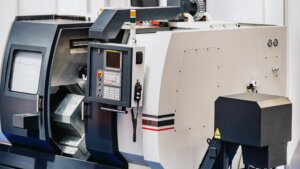
We ensure the optimal performance of our diverse range of CNC machines, including HAAS 3-, 4-, and 5-axis milling machines, through regular maintenance and calibration.
Our team of experienced engineers is continuously trained to handle complex geometries and tight tolerances, significantly reducing the likelihood of human errors. We excel in optimizing our CNC machining processes for precision parts, and we are meticulous in our use of high-quality materials, ensuring their proper handling at every stage.
Effective client communication is at the heart of our service. We provide rapid prototyping and instant DFM (Design for Manufacturability) feedback, using advanced software for process simulation to uphold our high standards.
Our collaboration with trusted supply chain partners and the valuable insights we gain from customer testimonials are integral to our continuous improvement and dedication to minimizing CNC machining defects.
Conclusion
In exploring the intricacies of CNC machining, we’ve delved into various aspects that influence the quality and outcome of the machining process.
Central to these are the material properties and the machining parameters which play a pivotal role in determining the efficiency and precision of CNC operations. From metals like aluminum and stainless steel to plastics and composites, each material presents its unique challenges and requires specific considerations to mitigate common defects like burrs, thermal damage, and tool wear.
Understanding these nuances is crucial for optimizing CNC machining operations, ensuring high precision, and maintaining the integrity of the machined components.