
Modern sectors like architecture, engineering, and manufacturing rely on computer programs to create designs of various parts and prototypes.
Therefore, understanding ‘what is g code’ becomes essential for anyone dealing with the area of Computer Numerical Control (CNC), 3D printing, or any computer programming language for designing machining parts.
This article will have an in-depth discussion on what is g code, its usage, working process, various types of G-code commands, and many other helpful information.
What is G-code?
G-code stands for geometric code. G-codes are also known as preparatory codes for CNC machines.
The instructions provided by G-codes tell the machine tool how to move in the (X, Y, Z) cartesian coordinate system.
In addition to the location instructions, the G-code also provides many other input such as speed and angle in the rotational axis, tool length offset, start point, stop point, feed rate, wait time, etc.
G-codes work in tandem with M-codes. M-codes stand for ‘Machine codes’ or miscellaneous codes. M-codes provide instructions on various functions of the machine that are not relative to the movements.
An example of M-code is M0, which means an end to the program.
Who Invented G-code Programming
The G-code was invented in 1958 by the Massachusetts Institute of Technology (MIT) Servomechanics Laboratory. The popularization and standardization of G-code occurred later in the 1960s by the Electronic Industries Alliance.
What is the Importance of G-code?
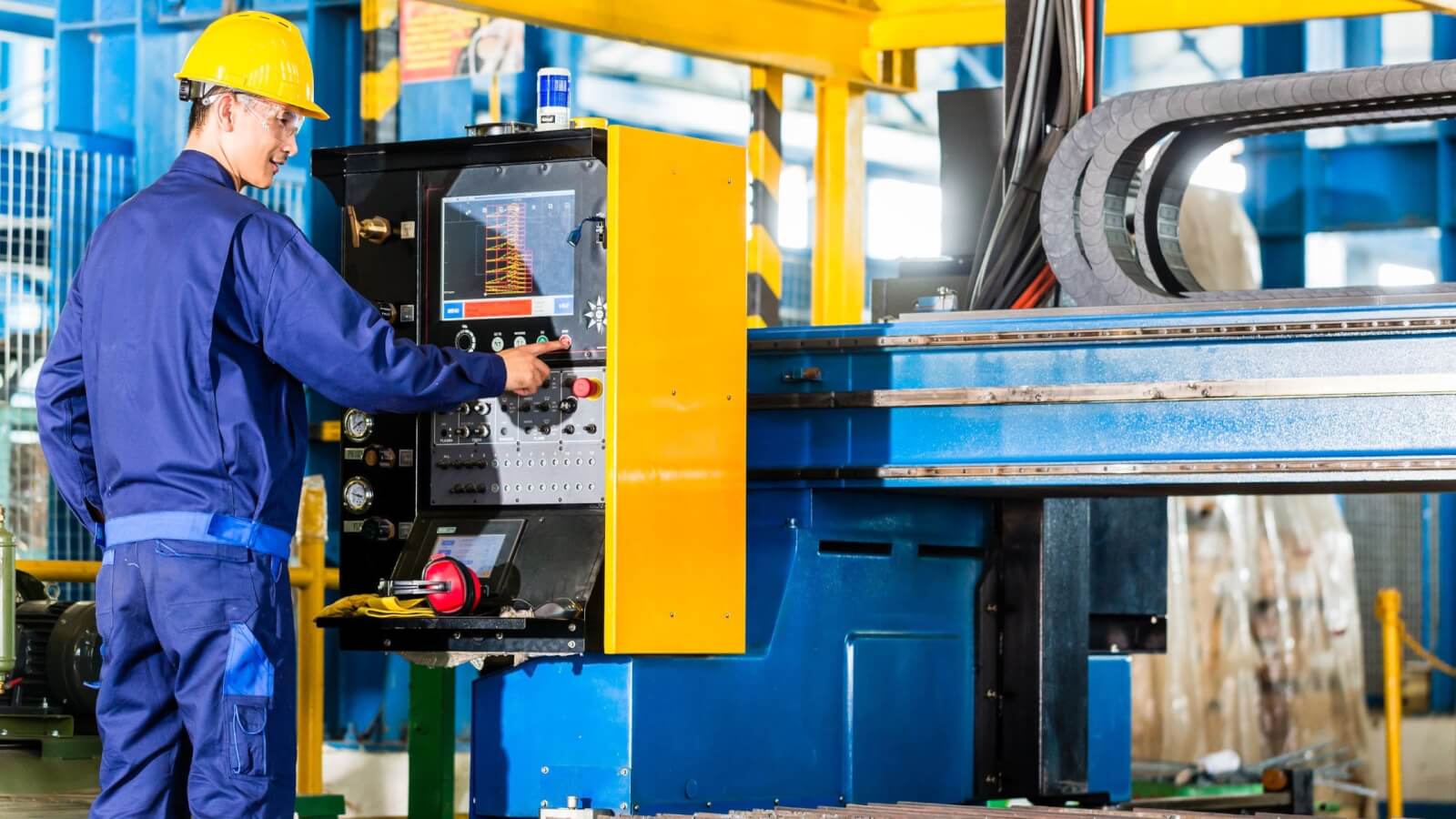
G-code is indispensable when it comes to the numerical control programming language. Machines by their very nature are not equipped with computer intelligence. They contain servomotors for the movement of various parts within them.
However, integrating the machines with microprocessor units can help in controlling the degree of movement of the motors. It can also make multiple parts of a machine work in tandem to accomplish the required operation.
However, the operators cannot directly communicate with the machine. A G-code acts as a communication language between the machine and the operator.
The G-codes are written in a way the control system of the CNC machine can understand. Using a G-code, the operator can tell a machine exactly what is required.
How Does a G-code Work?

G-code Working Process At Machine-End
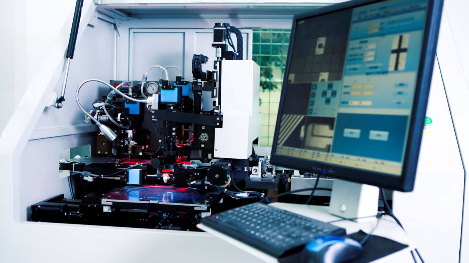
All CNC machines are built with a microcontroller that can interpret the G-code. The G-code is standardized in most CNC machines.
Some machines have advanced features or multiple axes that are outside the control of standard G-code commands. In this case, additional commands are written in the microcontroller to control the added functions.
When the internal control system software reads the commands, it interprets them according to the microcontroller instructions and provides movement directions to the various machine functions.
G-code Working Process At Operator-End
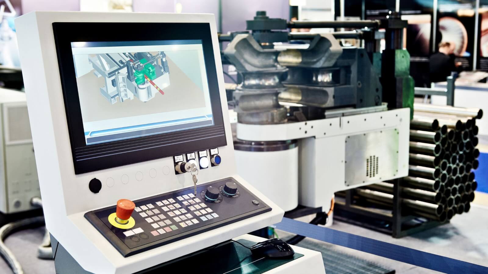
Generally, a Computer Aided Design (CAD) file is a precursor to the G-code programs. It creates a graphical visual in two or three dimensions of the required part. Modern software can automatically turn CAD designs into optimal G-code programming.
The benefit of this process is that the computers can do automated calculations for the best possible tool path and other settings. The G-code can automatically take into account features such as tool offsets.
If any changes are required in the G-code, a dedicated software called G-code editors are used. This editing stage is usually required for making customizations to the design.
The resulting G-code is not a standard for every machine due to the variance in the format and difference in machine features. Therefore, it goes through another software called post-processing.
It standardizes the G-code exactly as the machine is designed to read. This eliminates any possibility of bugs due to difference in various machine controller software. This finished G-code file is transferred into the CNC machine.
What is the Structure of a G-code?
The G-code is a combination of an alphabet and a number. The number can have multiple digits. The placement of space between the alphabet and the number varies based on the particular CNC machine.
Some examples of common G-code commands are: ‘G00’, ‘F10’, ‘M03’, etc. The commands don’t necessarily start with the letter ‘G’. However, ‘G’ is the most common letter that comes along in a G-code instruction.
Every line of the G-code programming language can contain multiple sets of instructions. This is also known as a G-code block. The CNC machine reads and implements the instructions in a particular sequence from left to right and top to bottom. Here are the representations of common alphabets used in the G-code:
- G: General machine movements
- F: Feed rate
- T: Tool change
- S: Spindle speed
- X, Y, and Z: Three linear axes in the cartesian coordinate system
- A, B, and C: Angular rotation axes around X, Y, and Z
What are the Different Types of G-codes?
A G-code can be divided into several different classes based on what it does. These classes are:
Positioning Commands
CNC machines have many different types of positioning systems that determine the motion control of the machine tool. The various G-codes for controlling motion are:
- G00: Rapid Positioning of Machine Tool
- G01: Linear Interpolation
- G02: Clockwise Arc Interpolation (Circular Interpolation or Helical Interpolation)
- G03: Counter-clockwise Interpolation (Circular Interpolation or Helical Interpolation)
- G90: Use absolute coordinates
Speed Commands
- G08 – G09: Increment or Decrement Speed
- G93 – G95: Choosing the Linear Feed Units
- G96: Constant Surface Speed
- G97: Constant Spindle Speed
Machining Operation Commands
- G81: Simple drilling
- G82: Simple drilling with dwell
- G83: Deep hole drilling
- G84: Tapping
Offset Commands
- G40 – G44: Tool Offset Values
- G53 – G59: Zero Offset Value
Miscellaneous Commands
- G61: Exact Stop Mode
- G04: Wait time
- G80 – G89: Process Description
How to Read G-code Commands?
It is fairly easy to read G-code commands with a little bit of practice. Here are some steps to help you identify what a G-code command will do:
1. Start by focusing on the alphabetical character of the command instruction.
2. Letters like ‘G’ and ‘M’ relate to machine operation. The number next to these letters are not for movement but to indicate what machine process or function will get affected. For example, G00 will provide rapid positioning of the machine tool. G81 will tell the machine to use the simple drilling cycle.
3. Letters like ‘X’, ‘Y’, and ‘Z’ provide the location in the coordinate system. The number next to these letters do not represent any code. Instead, these numbers provide the precise location in each of the axes. For example, X1 will tell the machine tools to move one unit in the X-axis.
4. Letters like ‘A’, ‘B’, and ‘C’ indicate angular position similar to the X, Y, and Z. The numbers next to these letters do not represent any action but the value of the angular rotation in a particular direction.
5. Letters like ‘F’ and ‘S’ relate to feed rate and spindle speed. The numbers next to these letters relate to the speed of the associated values. For example, F200 instructs the machine to use feed rate as 200 units. The particular units used are selected with the proper G93-95 codes.
6. Comments can be added in the g-code by using a semicolon (;) at the end of a line. Anything written in a line after the semicolon will not affect the operation of the CNC machine.
Therefore, a command such as G01 X10 F100 tells the machine tools to move at the coordinate X = 10 with a feed rate of 100 units.
What is an example of G-code Programming?
G-code programming language works for every type of CNC machine. The example below demonstrates a G-code program for a CNC mill. The objective is to machine a simple square with 20mm x 20mm dimensions in the linear XY plane.
- G21 ; Set all dimensions to millimeters
- G90 ; Set the s system to absolute positioning
- G00 Z5 ; Raise the tool at height of 5 mm above the workpiece
- G00 X0 Y0 ; Rapid positioning of tool at the point of origin
- G01 Z-1 F100 ; Lower the tool at a depth of 1 mm (height= -1 mm) with a feed rate of 100 mm/minute
- G01 X20 F200 ; Move the tool to the coordinate X= 20 with a feedrate of 200 mm/minute
- G01 Y20 ; Move the tool to the coordinate Y= 20
- G01 X0 ; Move the tool to the coordinate X= 0
- G01 Y0 ; Move the tool to the coordinate Y= 0
- G00 Z5 ; Raise the tool to its safe height of 5 mm
- M0 ; Program End Point. The machine stops running the program at this point.
This is just an example of a G-code program. The actual program can vary for different machines. For instance, some machines require G0, G1, and G2 instead of G00, G01, and G02.
An important thing to keep in mind is that ‘M30’ is not a G-code in itself. It is an M-code command related to the machine controller function.
What Machines Use G-code?
G-code is used in CNC machining and 3D printing. Among CNC machining, the different types of machines that use G-codes are:
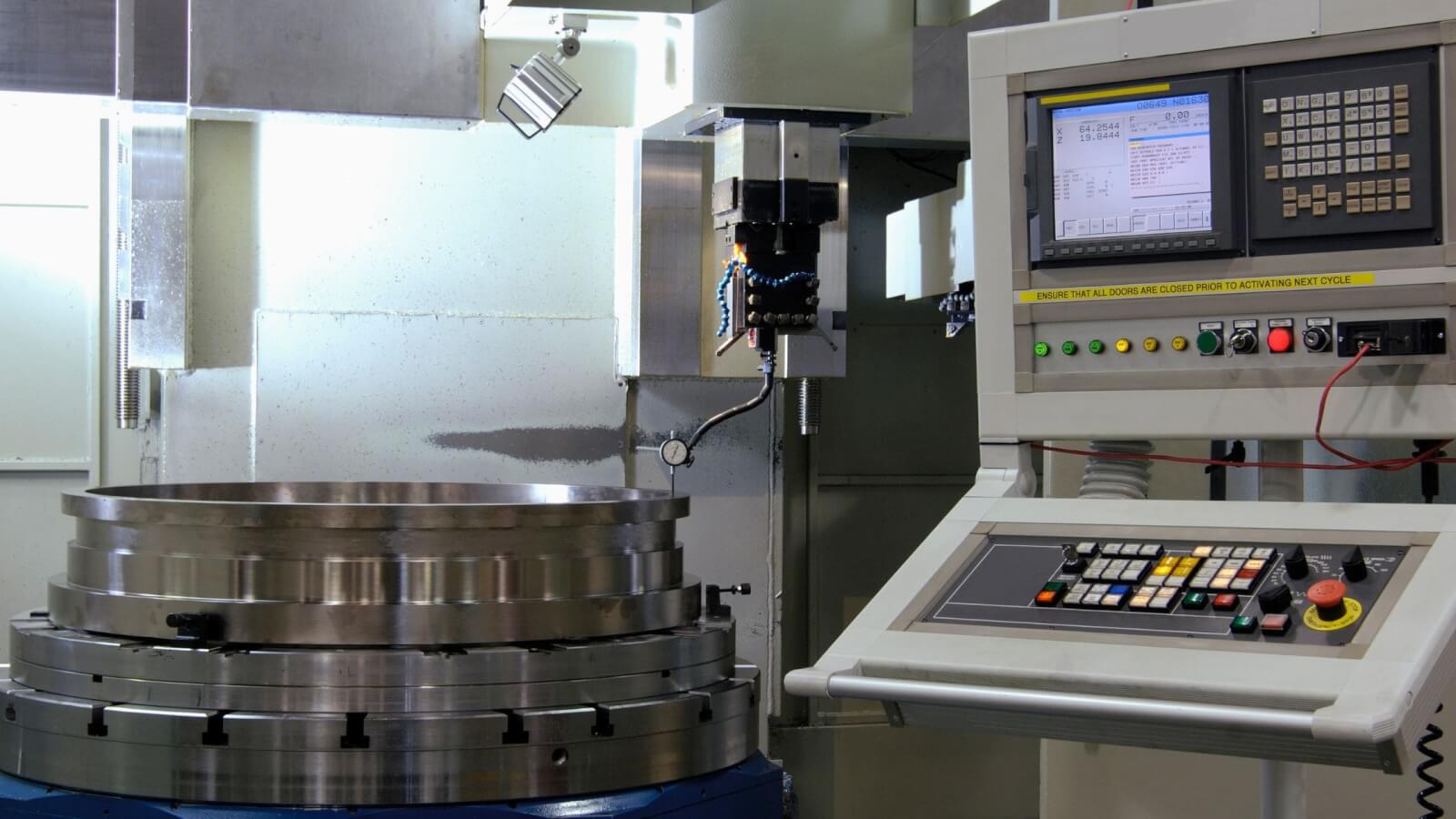
CNC Milling Machine
A CNC milling machine uses a rotary cutting tool against a stationary workpiece. The cutting tool for this CNC machine comes in many different shapes and forms. This leads to a lot of different types of milling processes.
CNC Turning Machine
A CNC turning machine uses a stationary cutting tool against a rotating workpiece. Turning machining is used to create symmetrical features on cylindrical and conical surfaces. A turning CNC machine has a helical tool path around the workpiece. Turning is used for the machining of external surfaces in the process of shaping. CNC lathes are based on the principle of a turning machine.
CNC Grinding Machine
Grinding is a type of machining that is used for fine machining of surfaces. It creates minimal material from the surface to smoothen it. Grinding is generally used as a secondary finishing process after other methods like milling and turning. Grinding can also remove the burrs made after welding and other joining processes.
CNC Drilling Machine

CNC drilling is a common process that creates holes in the workpiece by a drill bit. The purpose of the holes may be to fix screws, secondary assembly, or aesthetical. Drill presses are generally used after other machining methods. The diameter of the hole is limited. CNC boring is used when the required hole diameter is large.
CNC Routing Machine
A CNC router is a machine that is used for cutting of different materials. It generally combines a CNC system with a handheld router. The router can remove a very controlled amount of material from a surface. This provides the ability to carve intricate carvings.
CNC Laser Cutting Machine
A CNC laser cutting machine uses the heat of a highly focused laser beam to melt and cut the workpiece material. The laser has a very high level power focused through a system of optics. The cutting method is limited in terms of materials it can cut. Cutting any sensitive materials like plastics generate toxic gases which can harm the optical system.
CNC Water Jet Cutting Machine
CNC water jet cutting is an innovative technique that uses the force of high pressure water to cut through any material. The thickness of the water stream is less than a human hair. CNC programming can move the cutting head around. Waterjet cutters can pierce through high thickness of materials making them suitable for any application.
Who Needs to Know G-code?
G-code is a beneficial skill for people working with CNC machines such as the operator. CAM software is capable of generating the G-code for most CNC machines. However, understanding the G-code and knowing what it means allows the operator to micromanage the program. They can add any degree of customization to the program by modifying the G-code. Understanding the G-code also helps troubleshoot certain problems that may arise during the machining process.
G-code also turns out to be a useful skill for engineers, architects, and hobbyists. The application of G-code also comes up in 3D printing, further expanding the usefulness of this programming method.
What is the Best G-code Editor?
Some of the best G-code editing software are NC Viewer, Notepad++, Cura, gCode Editor, and G-code QnDirty.
All of these are free and come rich with features. There are also many paid G-code editing applications.
G-code editing software is generally used for making small changes to the program file. It also provides the option of replacing particular instructions with other instructions in the entire program. This find-and-replace feature is relatively quick with a G-code editor.
Are there any safety considerations or precautions to keep in mind when programming G-code?
Yes, there are important safety considerations to keep in mind when programming G-codes. G-code instructions should be written knowing the machine’s working limits.
Any wrong instruction can lead to tool collisions and breakage. Additionally, it is important to include compensations such as axis offsets. G-code program should also take into account factors such as the tool length.
What is the difference between G-code and M-code?
G-code and M-code handle different aspects of the CNC machine’s working process. The G-code handles aspects that relate to the movements of the tools in the X-axis, Y-axis, and Z-axis.
It also handles the tool rotation, feed rates, and other movement and speed controls.
M-code, on the other hand, handles various functions of the machine such as the coolant flow, program start and stop, calling subprograms, tailstock advancing and reversing, gear selection, etc. M-code commands are not related to the geometry of the part.
Both the G-code and M-code work together to create a complete CNC program.
Endnotes
G-code programming is a very useful skill for people working with CNC machines. The good thing is that G-code programming is fairly easy to learn with the right approach.
A good handle on G-code CNC programming provides the ability to craft even the most complex workpieces with a high level of quality and precision.
Frequently Asked Questions (FAQs)
Here are the answers to some common questions that are asked regarding G-codes:
1. Are G-codes universal?
Yes, G-codes are universal when it comes to CNC machines. All CNC machines work on G-code commands. Certain machines seem to have other features for designing parts that do not require programming. However, they still use the G-code for working. In such cases, the G-code layer is hidden from the end user.
2. Is G-code a Programming Language?
Yes, G-code is a type of programming language. The technical specification for this programming language is RS-274. CAM software can automatically generate G-code programs. Therefore, unless designing a complex part with many customizations, it may not require a dedicated programmer.
3. Is G-code hard to learn?
No, G-code is not hard to learn. In fact, any operator can learn simple G-codes easily within a short amount of time. The skills are then built up with practice and experience with the execution of codes
4. Do you have to be good at maths to understand G-code?
No, G-code does not require any special knowledge of mathematics. However, having a familiarity with the basics of mathematics can be helpful at times for the optimization of the program.
5. What are the 3 basic G-codes?
The three basic G-codes are G00. G01, and G02/G03. G00 instructs rapid movement of the machine tool at the required coordinate system. G01 provides instructions for the linear feed move. G02 and G03 relate to the clockwise and counterclockwise movements of the feed.