
Like any other manufacturing process, CNC milling requires the careful application of design for manufacturing (DfM) principles. Although CNC mills — and 5-axis machining centers to an even greater extent — can produce a wide range of parts in a variety of metals and plastics, there are certain design constraints that must be respected in order to produce viable parts.
Designing parts for CNC milling is not the same as designing parts for injection molding or extrusion. It even differs from CNC turning part design. This means CAD specialists should familiarize themselves with the physical limitations of the process before designing parts that cannot be practically manufactured.
Fortunately, our design guidelines for CNC milled parts are relatively simple, and as long as these guidelines are followed, your parts will pass inspection without issue.
What is CNC milling?
CNC milling is one of the main forms of CNC machining, the others being CNC turning and drilling. What sets CNC milling apart is its use of rotary cutters whose sharp edges can remove material from the workpiece. By contrast, CNC turning involves rotating the workpiece, and drilling is used exclusively to make holes.
Milling machines can be used for a wide variety of operations, thanks to the broad range of cutting tools that can be used. Tools like end mills, face mills, and fly cutters all perform different roles, allowing the machinist to make a variety of cuts in the workpiece.
CNC milling design constraints
When designing parts for CNC milling, there are a few important factors that determine what is an acceptable design and what isn’t. These include the machine setup or workpiece orientation, the shape of the cutting tool, the length of the cutting tool (i.e. how deep into the workpiece it can cut), and the workpiece material.
Workpiece orientation
A key consideration for CNC milling design is the machine setup or the way in which the workpiece is clamped to the worktable. Because the workpiece must be fixed to the worktable, one side of it is inaccessible to the machine tool, which means machinists must consider which way the workpiece will be oriented.
Parts with features on one face only are relatively easy to mill because the featureless side can face downwards, allowing the machine tool to reach the featured side. On the other hand, parts with details on all sides will need multiple setups: when one side has been milled, the workpiece must be removed from the workholding devices, flipped over, then milled on the other side.
Designers should design parts so they can be milled with the fewest number of setups, as each new setup requires time and calibration, ultimately adding to the cost of the part.
Tool geometry and diameter
Another unique feature of CNC milling that affects part design is the shape and diameter of the cutting tool. There are two important things to consider here. First, since the cutting tool is constantly rotating, it creates a circular cut. This makes it impossible to mill square inside corners. Why? For the same reasons that a circular Roomba vacuum cleaner can’t clean right into the corner of a rectangular room: its own geometry is a mismatch with the surroundings.
The diameter of the cutting tool also limits part design. A cutting tool cannot cut a cavity smaller than itself, so larger tools — while great for removing large chunks of material — cannot produce fine details.
Tool length
The final key design constraint for CNC milling is the tool depth, or how far the cutting tool can cut into the workpiece. On paper, it might appear that any hole depth can be milled as long as the tool is long enough. However, the longer a tool, the more likely it is to produce chatter: undesirable vibration that reduces the accuracy of the milling operation.
Workpiece material
Different metals and plastics have different levels of machinability: that is, the ease with which they can be cut by the CNC mill without deforming (or damaging the cutting tool).
During CNC milling design, the machinability of the material should be considered, especially when tight tolerances and fine details are desired. For example, a part made from aluminum 6061 may be able to accommodate deeper holes and achieve a tighter dimensional tolerance than a part made from a harder metal like stainless steel 440.
CNC milling design guidelines
We have looked at some of the limiting factors that determine how to approach CNC milling part design. Now we will look at some CNC milling design principles and rules to follow based on those factors. These include rounded corners, cavity depth, and minimum wall thickness.
Part size
One obvious consideration for CNC milling part design is the maximum part size, which is determined by the work envelope of the CNC mill being used. For reference, 3ERP’s largest 3-axis milling machine, manufactured by Haas, has a work envelope of 1016 x 508 x 635 mm. However, many mills are much smaller than this.
Also bear in mind that 5-axis machines tend to have smaller envelopes than 3-axis mills, so it may not be possible to combine many off-axis features with very large overall dimensions.
Align features
Because it takes time and money to set up the workpiece multiple times, designers should try to align features like holes and vertical walls on one face. This allows the machinist to mill all the features of the part with one setup.
Using a 5-axis machining center provides flexibility for off-axis features and holes, however, as the cutting tool can approach the workpiece from a greater number of angles without requiring a new setup.
Radii

Designers should remember that the circular shape of a cutting tool makes it impossible to mill square inside corners without the use of complex undercuts. Instead, internal corners will be rounded, with the size of the radius determined by the diameter of the tool.
That being said, using an internal corner radius slightly larger than the tool radius will produce better results, as it gives the tool clearance to turn the corner.
Additionally, specifying the same radius for each internal corner means milling can be completed faster.
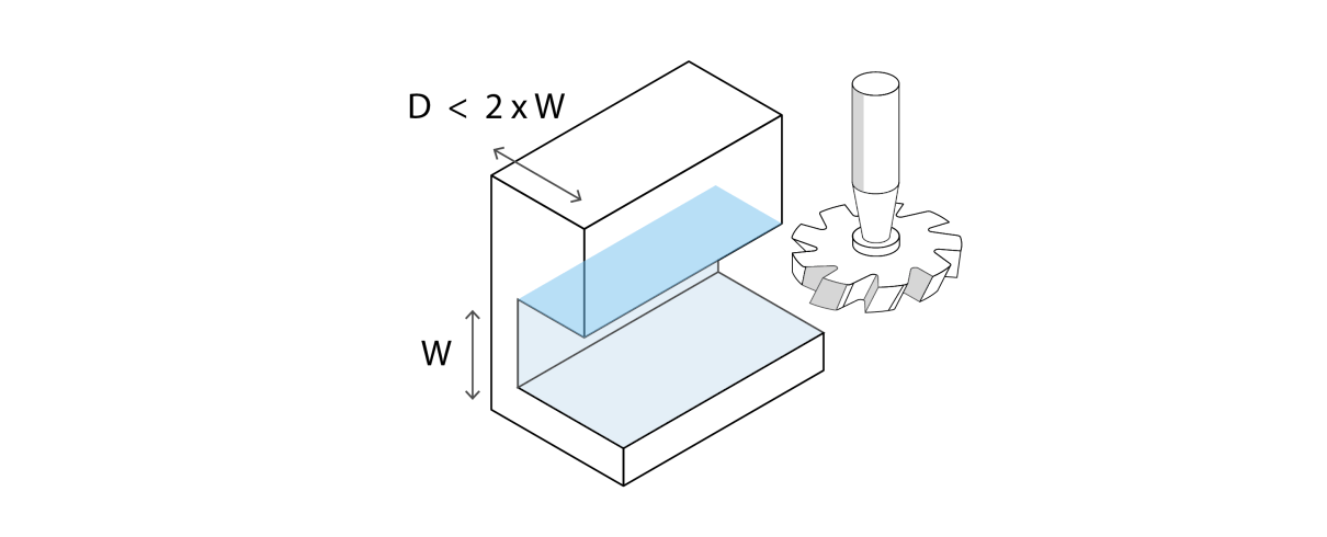
Cavity depth
To minimize chatter, tool deflection, and other issues, milled parts can only have cavities of limited depth. As a rule of thumb, cavities should be no more than four times as deep as they are wide.
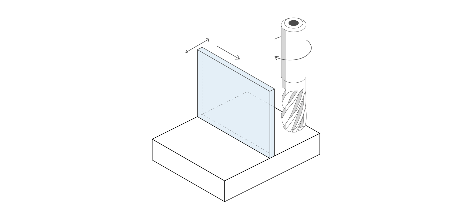
Wall thickness

When CNC milling thin walls — for part-strengthening ribs, for example — designers should not specify a thickness any lower than 0.8 mm for metals, or around twice that thickness for plastics.
Furthermore, the height of these thin walls should ideally be no greater than 10 times the wall thickness, i.e. a wall with 5 mm thickness should be no more than 50 mm tall.
Holes and threads

Designers should, where possible, specify holes and threads with diameters that correspond to standard drill bits and threading tools. Non-standard diameters are possible but must be cut with an end mill tool.
Hole depth must be considered as well as width. In most cases, hole depth should be no greater than about 10 times the diameter, though deeper holes can be made with special drill bits.
The base of a blind hole — a hole that does not fully penetrate the workpiece — will only be flat if cut with and end mill. If cut with a drill bit it will have a cone-shaped base.
Lettering

When adding text to the surface of CNC milled parts, it is much more efficient to engrave rather than emboss, as less material is removed. Furthermore, rounded sans serif fonts are much easier to mill than decorative fonts.
With hard metals, a font size of at least 20 should be used; softer metals and plastics can accommodate size 16.
Tolerances
Designers should consider realistic tolerances when designing parts for CNC milling. A standard tolerance is 0.1 mm; tighter values (down to around 0.01 mm) can be achieved, but at additional time and cost. Explore our precision machining services for more about tight-tolerance milling.
CAD software for CNC milling design
Most CAD applications can be used to design parts for CNC milling. However, the following two packages are widely used in the industry.
SOLIDWORKS
Developed by Dassault Systemes, SOLIDWORKS is a comprehensive CAD package which contains tools for validating CNC milling designs.
The popular CAD application comes with DFMXpress, a DfM tool in which the user can specify manufacturer-specified milling constraints such as a maximum hole depth to diameter ratio. The tool can also check for non-machinable features such as areas that cannot be reached by the cutting tool, highlighting any problem areas for the user’s attention.
Fusion 360
Developed by Autodesk, Fusion 360 is used by many engineers and machinists alike, with many features tailored towards CNC machining.
As with other CNC-oriented CAD packages, Fusion 360 allows for general and user-defined constraints, making sure the design does not have any impossible-to-mill features. Furthermore, because Fusion 360 is also a CAM tool, the software can actually generate toolpaths for CNC mills. If the design is not feasible, it will not be able to create these toolpaths.
CNC milling with 3ERP
3ERP has many years of experience with CNC milling equipment and will turn your designs into high-quality machined parts. You don’t need to worry about small design errors, either: after uploading your CAD files, we’ll send you DfM analysis if necessary so you can refine your design until it’s manufacturable.