Whether you’re making sheet metal, injection molded, or CNC machined parts, threads are a simple way to facilitate assembly of multiple components.
Over many decades of manufacturing, threads have become standardized, so components made by different manufacturers can still be joined together with standard fasteners.
However, despite the universality of threads, there are still many different types and sizes to choose from. Choosing a thread depends on several factors, including component thickness, join angle, and available threading tools.
This guide discusses the ins and outs of threads and threading, including the foremost types of thread, when to use them, and how to make them.
What are threads?
A thread is a helical ridged structure that follows a cylindrical or conical shape. In engineering, a screw thread refers to the ridge of either the screw itself (male) or the hole into which a screw fastens (female).
The function of a thread is simple: rotation of a screw moves it further into the hole, tightening a connection between two components.
The act of making male or female threads is known as “threading.”
Thread series and types
Threads can be classified by their series or standard, and by their type. Most threads fall under either metric (M) or unified (UTS) standards.
Common series/standards include:
- ISO metric threads (M)
- Unified Thread Standard (UTS)
- National Pipe Threads (NPT)
- British Standard Pipe (BSPT)
- British Standard Whitworth (BSW)
- Glass Packaging Institute threads (GPI)
Once the thread standard has been established, the exact type of thread is defined by a number or other variables. (See following section.)
Anatomy of a thread
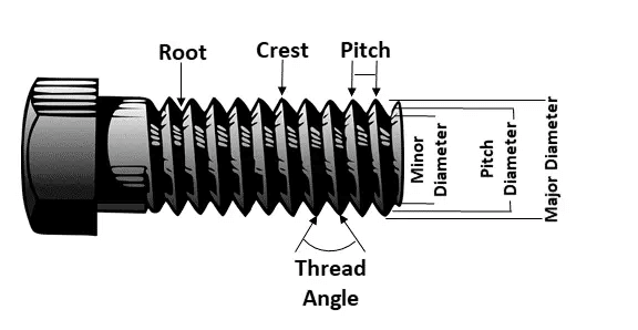
Threads can differ in many ways, including their diameter, pitch, and depth. These factors must all be specified when designing parts with threads, in order to ensure all components can be fastened together.
Aspects of a thread include:
- Thread size: Also the nominal diameter or major diameter, the thread size refers to the diameter of the widest part of the thread
- Minor diameter: The lower extreme diameter of a thread, i.e. the smallest diameter between each ridge of the thread
- Pitch: The pitch is the distance between one ridge of a thread from the next
- Lead: The lead is the distance along the screw’s axis covered by one 360° rotation of the screw; it differs from pitch only in multi-start / multi-entry threads
- Depth: The depth of a thread refers to how far the thread goes into a hole
- Taper: The taper of a thread is the degree to which the thread is conical as opposed to cylindrical
Ways to make threads
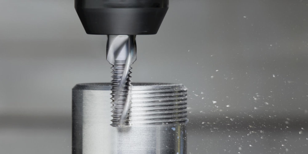
Most threads are made either subtractively, transformatively, or, in rarer cases, additively.
Subtractive threading techniques include taps and dies, in which a tap is used to create a female thread and a die used to make the male thread; single-point threading, in which a single-point tool moves linearly to create external or internal threads; and thread milling, in which a (CNC) mill is fitted with a thread mill cutting tool and cuts the thread according to a helical toolpath.
Transformative and deformative threading techniques include forming — using e.g. a fluteless tap — and rolling, which can take the form of flat die thread rolling, planetary thread rolling, two-die cylindrical rolling, or three-die cylindrical rolling.
Additive techniques are performed by 3D printing threads directly into or onto 3D printed parts. However, only high-end systems are capable of producing suitably accurate threads with acceptably tight tolerances.
Blind holes and thru holes
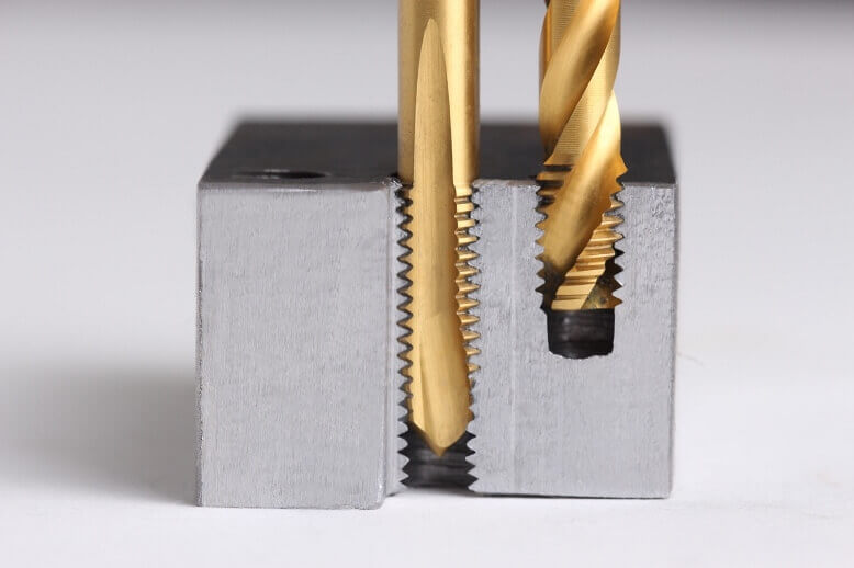
Thread holes can be divided into two categories: blind holes and thru holes. A blind hole is a hole that does not fully penetrate the part; it has an entry but not an exit. A thru hole, meanwhile, goes all the way through (making its depth equal to the depth of that section of the part).
Design tips
Designing parts with threads is not difficult, but it does require clarity for the sake of the manufacturer. In some cases, the thread will be made directly (3D printing etc.); in other cases, it is drilled after components have been fabricated.
Guidelines to follow include:
- Know your standards (and use them): Unless you have good reason not to, it is best to stick to the most common series (UN or M) and common sizes if possible. If you must compromise by making a thread marginally larger or smaller than intended in order to fit a standard size, it is often worth doing so.
- Specify thread depth: When designing blind holes, the thread depth will be smaller than the thickness of the wall being threaded. The exact depth should therefore be specified in the CAD design and/or in any technical drawings.
- Know your limits: Thread depths can be limited by thread diameter, material, and threading tool. If you specify too deep a thread, the part may fail or the manufacturer may simply be unable to execute the design.
- Use CAD software with threading tools: Threading is much simpler when your CAD/CAM solution offers tools for optimized thread design.
3ERP is a prototyping specialist with expertise in numerous manufacturing processes. Contact us for a free quote.