
Technical drawings (and the process of drafting) are a means of conveying information between engineers and manufacturers. Technical drawings usually complement digital CAD files, providing extra information that can’t easily be conveyed by a part’s shape alone.
In the world of prototyping and manufacturing, we typically deal with a certain subtype of technical drawings known as engineering drawings, and these contain information like material and finishing requirements, part information, and — most importantly — 2D and 3D views of the part from multiple angles complete with dimensions and tolerances.
This guide goes over the basics of technical drawings, discussing why you need them, what elements are typically included, and tips on how to prepare one.
Why we need technical drawings
Technical drawings have existed for centuries, predating today’s digital manufacturing technologies. Before computers existed, technical drawings were the main point of reference for manufacturers.
Today it is possible to design a part on a computer, then send a digital file from that same computer to a piece of machinery that will fabricate the part, all without the need for technical drawings at all. However, most high-importance manufacturing jobs — even those using digital manufacturing technologies — still demand the use of a technical drawing. Why?
Firstly, technical drawings verify what is contained in the CAD file, giving confidence to manufacturers that they are fabricating exactly what is needed. A perfect correlation between CAD and drawing indicates that there are no errors in the design. Once the part is finished, the drawing can then be used as reference during inspection.
Secondly, technical drawings can provide lots of other information not contained in a CAD file. Information conveyed through technical drawings may include:
- Tolerances for specific features
- Surface finishing requirements for specific surfaces
- Material requirements for specific components
- Internal or external threads
Thirdly, technical drawings can play a legal function. They are part of a purchase order and therefore part of a contract: if the manufacturer fails to deliver the parts as specified, the customer can use the technical drawing as evidence that the design has not been fulfilled; on the other hand, the manufacturer is protected from liability as long as it follows the technical drawing. (This does not apply if the CAD file is specified as the legal instrument over the drawing.)
Furthermore, manufacturers often prefer to receive a technical drawing along with a digital file because they can make a fast assessment of aspects of the part such as its geometry, dimensions, and potential cost.
And finally, technical drawings are the only internationally recognized way of communicating engineering instructions; there is no ambiguity, no confusion, and nothing that can potentially jeopardize the success of the project.
Summary:
- Verification
- Information
- Legal instrument
- Quick reference point
- Internationally recognized
Standards for technical drawings
Technical drawings and engineering drawings are subject to several universally recognized sets of standards. These provide guidelines for presenting drawings, helping to facilitate communication between different parties, including those who speak different languages.
The International Organization for Standardization (ISO) stipulates the use of ISO 128 for technical drawings and ISO 8015 for engineering drawings. The American Society of Mechanical Engineers (ASME) stipulates its own drawing standards, Y14.5 and Y14.5M.
According to the ISO document, ISO 128 “gives general rules for the execution of technical drawings (2D and 3D)” and is “applicable to technical drawing in the fields of mechanical engineering, construction, architecture and shipbuilding” including “both manual and computer-based technical drawings.”
Technical drawing views and other features
A finished technical drawing contains several different views of the object, allowing the manufacturer to easily interpret the engineer’s intentions. An engineering drawing for CNC machining or sheet metal fabrication will typically contain the following views and other features:
- Isometric views: An isometric or pictorial view shows the object rotated 45 degrees about the vertical axis and 35.264 degrees about the horizontal axis. The purpose of this view is to provide a three-dimensional view of the object with the illusion of depth.
- Orthographic views: Orthographic views are two-dimensional depictions of the object as seen from the front, right, left, top, bottom, or back — known as the primary views. The combination of these orthographic views is known as a multiview projection. In most cases, just two or three orthographic views are needed to convey the requisite information, and a drafter will typically include the minimum required.
- Auxiliary views: Auxiliary views are any additional 2D views from angles other than the six primary views.
- Section views: Section views show a cross section of the object along a specified cut plane. They are used to show internal details of a part and are usually placed in line with an orthographic view.
- Detail views: Detail views highlight critical or complicated areas of an orthographic view.
- Title block: The title block contains information such as the part name, company name, part number, drawing number, material requirements, finishing requirements, coloration requirements, scale used, and standards used. It is typically placed in the bottom right corner of the drawing.
- Notes list: Notes to the user of the drawing may be included. These may be general notes or flagnotes and can be placed anywhere along the edges of the drawing.
How to quickly prepare a technical drawing
Thanks to modern CAD software, preparing a technical drawing does not necessarily require the services of a professional drafter. This section will discuss how to create a technical drawing using CAD software, not how to draft on paper — a process that should be left to a specialist.
From model
The easiest way to prepare a technical drawing is to generate one automatically from a CAD design. In SolidWorks, for example, this simply involves selecting Make Drawing from Part/Assembly in the Standard toolbar, then selecting a predefined template. The software will automatically generate views and features as selected, and the drawing can then be exported.
There are many advantages to creating technical drawings from models. For example, parts can be digitally “assembled” to ensure they fit together, and it may be possible to run simulation tools to ensure the parts will work properly.
From scratch
It is also possible to prepare a technical drawing from scratch using CAD software. This may be preferable if you do not have CAD experience and have not yet created your part using the CAD software. This is effectively like drafting on paper, but using digital tools that can reduce chances of error.
Note that creating a technical drawing from scratch does not allow for digital assembly or simulation.
Regardless of your method of preparation, all technical drawings should include:
- Geometries / views
- Dimensions
- Tolerances
- Material requirements
- Finishing/color requirements
What to include on a CNC machining technical drawing
When preparing a technical drawing for CNC machining, there are some specific features that may need to be added. These include:
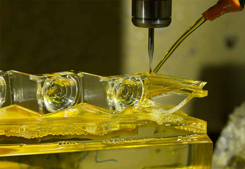
Tolerances for specific areas: CNC machining is unlike other manufacturing processes in that several machine tools may be used to machine a single part. For example, machining may begin with roughing before end-milling for detailed features. Because of this, engineers may feasibly specify different tolerances for different areas of the part, with critical areas machined more slowly with finer cutting tools.
Hole callouts: Holes, which include features like countersinks, are common CNC machining features and are often identified on detail views.
Thread specifications: Since threads are made in standard sizes, it is helpful to assign each thread its relevant thread size, rather than its dimensions in millimeters.
What to include on a sheet metal technical drawing
When preparing a technical drawing for sheet metal fabrication, there are some specific features that may need to be added. These include:
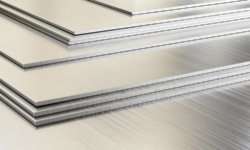
Material gauge: Material gauge — the thickness of the metal — is not relevant to processes like CNC machining, but it is crucial to sheet metal forming.
Grain direction: For e.g. stainless steel parts, it may be necessary to specify the direction of the grain in a technical drawing, because grain has a significant effect on actions like bending. Bending with the grain (longitudinal) requires less force but can cause cracking on the outside bend radius; bending across the grain (transverse) requires more force but protects the outside of the bend.
Torque requirements etc. for assembly: Different materials and gauges can accept different levels of torque when fitted with screws during assembly.
Weld locations: Locations (and dimensions) of weld points should be specified in the drawing.
Dimensions of bends, countersinks, holes: Dimensions of features like countersinks should be specified.
What to include on an injection molding technical drawing
When preparing a technical drawing for injection molding, there are some specific features that may need to be added. These include:
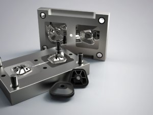
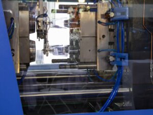
Acceptable draft: In many cases, the injection molding company will determine the minimum required draft angle to facilitate ejection from the mold. However, if the engineer decides that certain features cannot accept a high degree of draft (because of the product’s end use, for example), this should be specified in a note on the drawing.
Gate, ejector pin & parting line location limitations: In most cases, the molding company will decide on gate and pin placement. However, to avoid impractical gate and pin locations, the technical drawing can stipulate any unacceptable locations, while leaving the final decision to the molding company.
What to include on a die casting technical drawing
When preparing a technical drawing for die casting, there are some specific features that may need to be added. These include:
Acceptable draft: As with injection molding, the casting technical drawing may stipulate any restrictions on draft angles.
Gate & parting line location limitations: As with injection molding, the technical drawing may stipulate any unacceptable gate or parting line locations while leaving the final decision to the casting company.
Minimum wall thickness: The technical drawing may stipulate a specific or minimum wall thickness in addition to the given dimensions.
What to include on a plastic/aluminum extrusion technical drawing
When preparing a technical drawing for extrusion, there are some specific features that may need to be added. These include:
Stock size: The required metal stock size may be specified on the technical drawing. However, it is usually not necessary.
Grain direction: As with sheet metal parts, the technical drawing may specify a metal’s grain direction to ensure it is strongest in a certain direction.
Exposed surfaces: An extrusion technical drawing may indicate exposed surfaces that require a greater attention to detail.
Hole callouts: Holes are often identified on extrusion technical drawings in detail views.
3ERP is a prototyping and low-volume manufacturing specialist with many years of experience. If you’re unsure whether you need to submit a technical drawing, talk to us directly. If you have one ready, upload it with or with your CAD file to get a fast free quote.